Defining Specification Features | |
| |
- Click to select the options of your choice.
-
Click
 , and select the
type and the object type.
- Alternatively, select a type in 3D area or in the tree when clicking in the type editor. You can then select a specification feature, a typed product, or other geometrical entities with the type extension added (such as those created in Building) to retrieve the type.
- The selected type is memorized and proposed when you next enter Capture Component Specifications.
- The object type is optional. For a specification pattern, it applies to all specification features contained in the specification pattern.
-
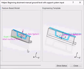
To display a preview of the selected object type in a side panel, click
Template Helper
 .
A template viewer opens next to the Capture Component Specifications dialog box and displays the shape of the object type and axis systems.
In the Helper, you can move and zoom in the object type. Click again the same input and the object type moves back to its initial position.
To close the Helper, click
 or Close or
-
From the Specifications list, choose a creation method
(Individual Specifications, Selection
Pattern, Curvilinear Pattern or Linear
Pattern).
By default, Individual Specifications is selected, non-patterned specification features will be created.
- When creating specification features from a pattern, select a pattern from the list.
-
If you have selected Individual Specifications to create
non-patterned specifications, select either points or axis systems.
- Multi-selection is available.
- By default, existing specification features cannot be selected.
- Only specification features that existed before launching the command can be selected. The specification features that are under creation cannot be selected.
- Use the same context menu commands to create a point or an axis system. The
corresponding dialog boxes are displayed accordingly.
- Point Definition (Create Point)
- Axis System definition (Create Axis System)
- Axis System definition from robot (Create Axis System from Robot)
-
Expand Axis System Modification.
Modifications apply to all Specification Inputs.
The context toolbar appears.- Reverse X Direction, Reverse Y Direction and Reverse Z Direction reverse the direction of the specification features while preserving the right-handed axis.
- Z Direction lets you select a linear geometry used as the Z direction of the specification. You can also select the default or the Absolute Z direction from the context menu.
-
When creating a specification feature from a point, use the context menu in Reference Axis System.
- Default (Absolute): The axis system is created in the absolute coordinate system.
- Current Axis System: The axis system is created as the current one.
- Create Axis System: You create one axis system from the dialog box that appears.
- Create Axis System from Robot: Position the Robot, then select this item to create an axis system from the Robot position.
- Optional: If the selected object type contains a feature-based model or a product-based model or both, you can access the Content Specification section.
- If the object type contains a feature-based design whose required inputs are complete, click Process to instantiate user features.
- Click List View to list the specification features with their destination in the tree and their type.
- Click OK to create the specification features.
-
To edit existing specification features:
- Double-click an existing specification feature.
- Right-click an existing specification feature, and select Definition in the object's menu.
-
To show specifications in the work area, click Show All Component
Specifications
 in the
View section of the action bar.
Notes:
in the
View section of the action bar.
Notes:- To hide the component specifications, click Hide All Component
Specifications
 .
. - To show only the free component specifications of a product, click Show
Free Component Specifications
 .
.
- To hide the component specifications, click Hide All Component
Specifications
| See Also |
| More help on this topic |