Here are the characteristics of the UDF-based Cross Section:
The UDF-based cross section can contain the following definitions, as outputs of the UDF:
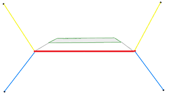
The schema below illustrates about the structure:
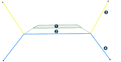
 Subgrade layer 1
 Subgrade layer 2
 Excavation profile
 Filling profile
Each geometrical definition must be typed manually:
- The UDF outputs, called subgrade layers, must be typed as Subgrade
Layer. They can be further typed by adding an Object Type of
Subgrade Layer type. Typing is performed through the
Define Specification
 command.
- The UDF output, the excavation profile, must be typed as Excavation
works. Typing is performed through the Define
Specification command.
- The UDF output, called Filling profile, must be typed as Filling
works. Typing is performed through the Define
Specification command.
- Note that there is no explicit UDF output corresponding to the earthwork surface.
It can take parameters and geometries as inputs. For example, the slope angle can depend on
different terrain layer characteristics. The slope is almost vertical for a hard-rock layer,
and much smaller for a soil terrain. An UDF allows to compute automatically these slope
angles if the UDF takes these different terrain layers as inputs.
Table 1. Two ways of defining excavation and filling profiles
| Type |
Remark |
Type A

|
- Both excavation and filling profiles are continuous polylines.
- The excavation and filling profiles must be in contact.
- The shared common segment
- is used in the Subgrade commands to create a common surface,
- is ignored in the Earthwork commands.
- It is accepted by both the Earthwork and Subgrade commands.
|
Type B
|
- At least one profile is a discontinuous polyline. The other one can be a
continuous or discontinuous polyline.
- It is not mandatory for them to share a common segment but they must have
shared points.
- If both profiles are discontinuous, it is not accepted in the Subgrade
command.
- It is accepted in the Earthwork Design only.
|
|
|
If you define excavation and filling profiles with continuous polylines (Type A), such
profiles can be used in both Earthwork and Subgrade commands.
If you define excavation and filling profiles with discontinuous polylines (Type B), such
profiles can only be used in Earthwork commands. Subgrade commands cannot accept such
profiles.
At least one profile is a discontinuous polyline. The other one can be continuous or
discontinuous polyline.
It is not mandatory for them to share a common segment but they must have shared
points.
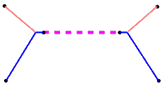
It is possible to define shoulders in this type of profiles: The segment common to
excavation and filling profiles is considered as a shoulder, as shown below:

Shoulders.
The
internal points for each excavation and filling segments must be identical geometrically.
The segments that are common to both excavation and filling profiles are considered as
shoulders, in the same way as for a sketch-based profile.
The excavation and filling profiles must be defined as UDF outputs.
You can create a line linking the two internal points respectively on left and right sides
of the cross section, and declare this line as the main result.
Earthwork Design commands only accept the UDF which contains excavation and filling
profiles. If the UDF also contains subgrade layer definitions, they are ignored.
Subgrade Design commands accept the UDF which contains subgrade layer definitions and/or
excavation and filling profiles of Type A. If subgrade layer definitions exist, the subgrade
layers will be generated. If excavation and filling profiles exist, earthwork results will
also be generated.