Defining or Editing the Bridge Layout | ||||
|
| |||
-
To define the bridge layout, select one of the following Deck
Isostaticity modes, under the Bridge Layout area:
- Hyperstatic: The deck contains only one continuous span from the start abutment to the end abutment.
- Isostatic: The deck contains several spans. The number of
spans is equal to the number of total piers minus one.
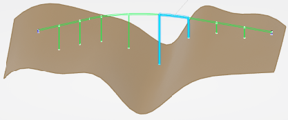
- Combined: The deck can be partially hyperstatic (two or three spans can compose one span). It can contain one hyperstatic span and one isostatic span, because it is possible to group several spans into one hyperstatic span in this mode.
-
If you choose the Combined mode, it is possible to define a
locally hyperstatic span with the help of contextual command by using the following
procedure:
-
Click a span.
A local panel is displayed, with the Start Support and the End Support of the selected span.
-
To define the abutments of the bridge, select the start support:
-
and the end support:

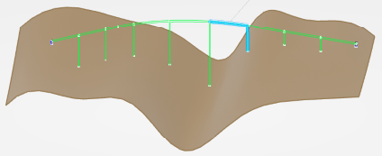
The bridge is partially hyperstatic. The continuous span is highlighted in the 3D area.
-
Click a span.
-
In the Layout View list, select Linear or
Wireframe.
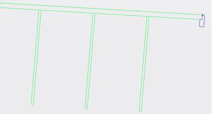
If you choose Linear, the piers and abutments have a linear shape:
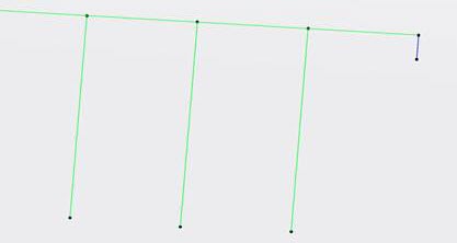
If you choose Wireframe, the piers and abutments have the rectangular shape:
-
To apply the same Object Type for both the start and end abutment supports, in simple
and custom bridges, select the Reverse End Support option.
The option is selected by default. If the end support specification set is not yet initialized, the option is ignored.
When it is selected, the axis system of the end-support specification feature is automatically reversed. The same Object Type can also be used for n supports.
When it is cleared, you need to choose another Object Type for the end support, that is different from the start support's, and to invert the X and Y directions of the axis system in the Capture Component Specifications dialog box.
-
Edit bridge parameters in the Bridge Design Assistant dialog box
or in the 3D area.
Here is a description of the parameters of a custom bridge:
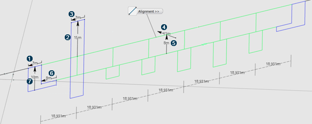
 Abutment
Length
 Tower Height
 Support
Length
 Deck Width
 Deck
Height
 Abutment Seat
Length
 Abutment
Height
Abutment
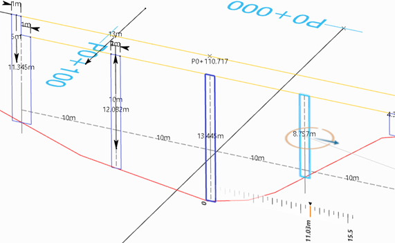
HeightOther parameters can be considered in a simple bridge:
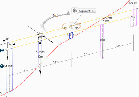
 The
support's height is the projection retrieved by the alignment (black line) and the
terrain (red line).
 If the projection does not
exist when the terrain is above the alignment, the Support Height
parameter can be used.Note: The same color convention is applied to both simple and custom bridge layouts:
If the projection does not
exist when the terrain is above the alignment, the Support Height
parameter can be used.Note: The same color convention is applied to both simple and custom bridge layouts:- Blue for the supports and abutments.
- Yellow for the deck.
- Red when some parameters are not allowed.
- Optional:
Edit the height, width, and length values of the curvilinear patterns, in the
Parameters table.
After editing a value in a cell, press Enter to validate.
The layout representation of the bridge will be kept as a permanent feature result. After the bridge generation:- Bridge results appear in dedicated nodes in the tree.
- To edit the bridge specifications, double-click the Bridge Set node.
-
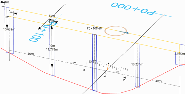
To move the bridge globally, select the alignment (deck) and use the ruler.
-
To move the bridge locally, select any support but the middle support and, use the
ruler.
