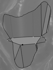
Create Platform Cross Section
You can create a platform cross section that is an input necessary for the platform creation.
Before you begin: After designing a platform, the node
Earthwork containing a
Platform Stretch Set is created in the
tree.
-
From the
Civil Engineering section of the
action bar,
click
Platform Cross Section
 .
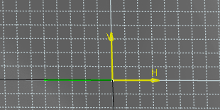
The Platform Cross Section Sketcher opens, allowing you to edit excavation profile and filling profiles. The green line displays the platform location always on the left side for scanning along the curve or surface.
-
Click
Excavation Profile
 from the
Platform Cross Section section of the
action bar.
You create a one-side profile, only on the right. It consists of a polyline, corresponding to the right side of the platform.
-
Draw the side of the excavation profile in the
3D area.
The platform profile is displayed with a green line.
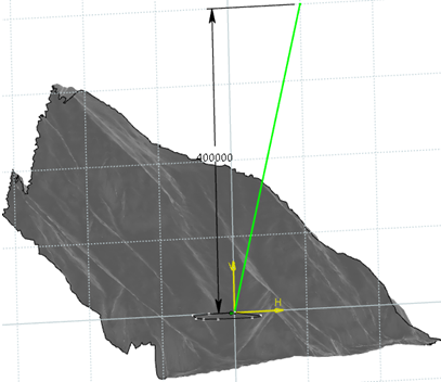
In the Excavation Profile dialog box, you can see the status of the side of the profile before
 and
after their creation
  .
. The Platform Cross Section node is created in tree.
-
Double-click anywhere in the 3D area to validate or click
OK in the
Excavation Profile dialog box to create a 3D
output profile corresponding to the excavation profile.
A Cross Section node is created, representing the geometry that will be removed or filled. You can edit the profiles in the same way as for any sketch polyline.
Tip: After creating the profile, the status icon is green and the Create side 1 profile button changes into Edit side 1 profile in the Excavation Profile window. -
To add segments to the first created profile, click
Edit side 1 profile next to
 .
The cursor automatically moves at the end of the profile and you can add other segments to the existing profile. To delete this side of the profile, click
 .
.
-
Click
Filling Profile
 from the
Platform Cross Section section of the
action bar.
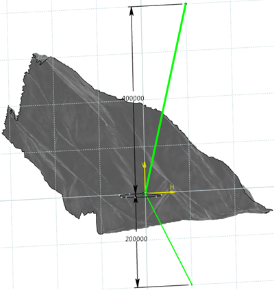
The creation of the filling profile is the same as for the excavation profile. You must create a one-side profile, only on the right. It represents the geometry that will be added on the ground. It is displayed with a green line.
-
To go back to the
Civil Engineering 3D Design,
click
Exit
 .
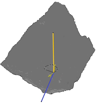
A platform cross section is created. The Filling profile is blue and the Excavation is orange:
-
To modify the profile with the new one created, edit the
platform:
- Select Platform under Platform Stretch Set in the tree.
- Click inside the Platform Cross Section box of the Platform Earthwork window.
- Select a cross section in the tree.
-
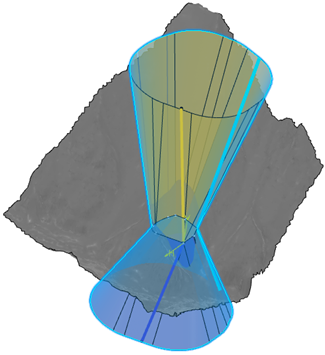
Click
Preview:
-
Click
OK.

-
To visualize the modified terrain, hide the platform and
excavation/filling works under
Earthwork > Platform
Stretch Set:
