Modifying the Geometry After a Station Equation

After creating your horizontal alignment, you may want to modify this alignment after a certain point thus keeping the stationing unchanged before this point.


Before you begin: You must have created and opened an horizontal alignment.
See Also
About Multiple Stationing and Station Equations
Modifying the Geometry Before a Station Equation
Modifying the Geometry by Creating Two Station Equations
  1. From the Civil Engineering section of the action bar, click Stationings .
  2. In the Assistant, click Split stationing and keep back labels and click the alignment to split it.
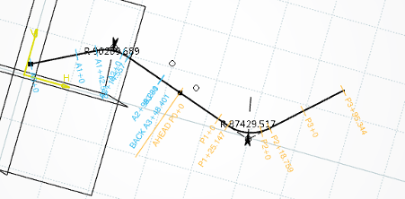
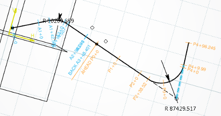
    The station equation is created showing two different sections. The coordinates of the station equation are displayed (A3+48.401 below) and the label of the new station is P.

    You can then modify the alignment after the stationing by dragging it:

    Note: Station equations are also displayed in the tree under the Alignment\Alignment points node.
  3. Optional: Modify the name of the labels clicking once in the corresponding label cell and entering a new letter.
  4. To customize your display, use one of the options available in the Display section of the Alignment Assistant.
  5. Optional: You can modify the minor and/or major intervals using the up and down arrows.

    The intervals defined are driven by an xml file stored in Data Setup. For more information, see Building and Civil Resources.

  6. Optional: You can modify the color of the stationing clicking the color square next to the label name and picking a color in the color picker.

Notes:
  • To delete a stationing, click in the Stationing Assistant.
  • You can create as many station equations as necessary.
  • Station equations are also visible in vertical and 3D alignments. However, they cannot be edited nor created in vertical or 3D alignments.