Creating a Curvilinear Pattern | |||||
|
| ||||
-
To display the pattern information, click
Preferences
 and select the following options:
- Display distances: In-between the axes.
- Display axis rotation: Values on the axes.
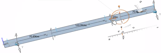
You can visualize the pattern group distances in-between the axis. Distance values are compatible with the pattern definition.

Notes:- Pattern distance visualization is not editable.
- Modifications related to a group axis origin affects the display of distances.
-
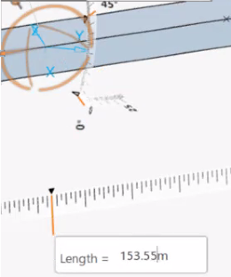
To edit the group length, use the Robot.
Once an axis is selected, the Robot is activated to displace a group or internal axis. A ruler is provided if the group length is editable.
Notes:- The Robot is proposed to handle group length edition helping you to access the editable distance for a selected pattern group. Ruler edition helps you to apply precise numeric values that are compatible with the pattern definition and design unit.
- When the ruler is available, the user-defined pattern is in count mode with no pre-existing snapping constraints, the group is also on the curve: as a result, the group length is editable.
- Once you have applied a precise displacement, for example 100m, the ruler allows to define the group length with this numeric value. As it is in count mode, the number of internal axes within this group should be the same as before with an updated computed spacing.
- If you decide to drag the arrow, the Robot helps you to apply the end result.
-
To move the internal axis with the help of the manipulator, drag the arrow
along the direction of the curve.
You obtain a precise displacement with internal axis edition. If you click a value on the ruler, a rule editor box appears and you can enter a precise numeric value.
If the distance is editable, the ruler is displayed later on, providing the possibility to enter a precise value for the parametrized distance. The current parametrized distance is the distance between the modified internal axis and the beginning axis of the group.
Notes:- Modification to internal axis is unitary. Current selection and modification behaviors should stay consistent with the manipulator mechanism.
- You can edit internal axes in both Axis mode and Group mode.
-
To apply a pattern compatible displacement, choose either of the following
commands in the Group panel:
- The Start of the group
The Previous axis of the selected axis
- The Next axis of the selected axis
Notes:- By default, the internal axis is determined by the current pattern group definition. Once parametrized (modified), the beginning axis of the group is the reference for displacement. This reference cannot be changed for root references (for example, start and end limits.
- The component and the ruler editor provide a visual assistance to determine the reference, the modification is a unitary modification on the selected internal axis that may or may not lead to a chain reaction. For example, you change the distance which does not affect other axes if they are not referencing the selected axis.
Modification Expected Behavior Expected Result Not modified The result is managed by the definition of the selected pattern during creation. 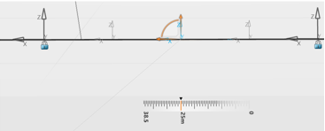
Unitary modification Select the option to reference the previous axis while selecting an internal axis in Axis mode. There are no other axis referencing the selected axis in the created pattern. 
Chain reaction Displacement chain reaction may occur with unitary modification when other internal axis are referencing the current one. In general, there are three types of references: the start, the previous axis, the next axis. 
Notes:- It is possible to have all internal axis referencing entirely the previous axis or entirely the next axis.
- The three reference types are not applied to the start and end limits, which are fixed with their own references.
- The actual availability of these references to the internal axis is determined together with their reference’s references.
- When there are some internal axes that are referencing the previous axis, while the rest are referencing the next axis. Mutual referencing leads to unpredictable results, and a warning is displayed.
- The Start of the group
-
Rotate the Robot or use the ruler to input an exact rotation value in Axis
mode.
It applies a unitary rotation to the selected internal axis.

Notes:The command stores the modified local rotations using a modifier on the internal axis in the pattern. The arrow of the Robot should be able to position itself according to the position of the selected internal axis based on its reference. The rotated angles are preserved according to the following definitions:
- The horizontal rotation
- The vertical rotations defined by the tangent and normal planes.
Indicator Definition Example Horizontal rotation The first direction of the internal axis is defined by the pattern. This rotation applies to change from this direction to another on the plane defined by the normal.
Horizontal rotation (60 degrees) 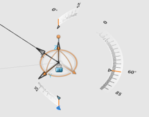
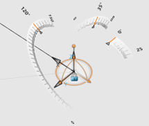
Vertical rotation There are two types of the vertical rotations: the longitudinal and lateral rotations.

Vertical rotations (120 and 35 degrees)
You obtain:

Notes:- The Robot is expected to adjust itself before and after each rotation to find the correct direction based on the selected internal axis from its reference.
- You can rotate the Robot freely. The result of the rotation can stay in a reasonable range. The Robot can calculate the correct angular increments and marginal values between a defined range of 0 to 360 degrees for each of the angular ruler editor (X, Y, Z).
The group axis origin is specific to each group. Modifications applied to Group2 will not impact the subsequent Group3 in the example. When the modified axis origin of the group is hybrid, you can distinguish visualization specific to the group.

-
To display the modified group axis origin, when group axis origin is
modified on the selected group, select the Start of the
group option of the Local Axis
Modification area in the Group1 panel for example.
Once the Specific to group option is activated, the modified translations on X, Y, and Z and the offset modifications are presented
The group axis origin is modified on the selected group.
This clarifies the group positions to the reference curve.
Notes: When a group is selected in Group mode with the modified group axis origin (either translation or offset),you can see two types of indicators:- The translational values: Violet trihedron.
- Theoffset values: Green trihedron.
Indicator Definition Example Translate trihedron The position of the group applies modifications to group level (all the axes of the group) with a global position in X, Y, Z. This an absolute translation for the entire group. One modification (X = 10m):

Two modifications (X=10m et Y=15m):
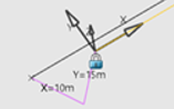
Three modifications (X=10m, Y=15m, et Z=11m):
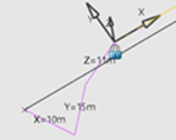
Offset trihedrons Each internal axis has its own offset trihedron that is relative to its reference (for example, the local trihedron according to the curve morphology). One modification (X=5m):

Two modifications (X=5m et Y=10m):
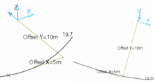
Three modifications (X=5, Y=10m, et Z=8m):
when there is no hybrid, the original reference is used.
Notes:- The group axis origin can be modified to have either positive or negative translations or offsets in the normal direction defined by the Z-index. The tetrahedron must respect the globally defined chirality of the modification.
- Group axis origin visualization is expected to be visible if it is activated and modified.
-
To define the orientation of
X Direction for a given axis (as shown in the
figure below), do one of the following:
- By Default: The X direction is tangent to the curve.
- Chord From Previous Axis: The X direction is defined by the chord linking previous axis to current axis, except for the start axis which is tangent to curve or has a user-defined direction.
-
Chord to Next Axis: The X direction is defined
by the chord linking current axis to next axis, except for the end axis which
is tangent to the curve or has a user-defined direction.
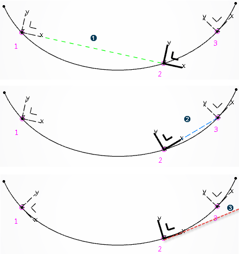
 Direction defined by the chord from previous axis (1) to
current axis (2)
Direction defined by the chord from previous axis (1) to
current axis (2)
 Direction defined by the chord from current axis (2) to
next axis (3)
Direction defined by the chord from current axis (2) to
next axis (3)
 Direction tangent to curve
Notes:- If X orientation is defined by Chord from Previous Axis or Chord to Next Axis, then the X direction is computed based on the above definition, instead of the direction tangent to the curve.
- If the axis orientation is defined by Direction Imposed, the above X direction is used as input to compute the x direction of the result axis.
- If X orientation is defined as By Default, the start or end X direction selection is ignored, and its editor is not displayed.
- If X orientation is Chord from Previous Axis, then you can select a chord direction for the start axis by first clicking on Start Chord Direction editor.
- If X direction is Chord to Next Axis, then you can select a chord direction for the end axis by first clicking on End Chord Direction editor.
- If start or end X direction is not selected, it is the tangent to curve which is used for start or end axis.
- If Align to Reference is selected in the Axis Orientation box, the Projection Direction box appears which is useful if the Measure option is On Projected Curve.
The Support Surface option is displayed in the dialog box, if Axis Orientation is Tangency Imposed and X Direction is By Default. In all other cases, the Support Surface option is hidden. If this option is selected, the Y direction of all axes is tangent to the input surface. If the curve does not lie on a support surface, an error is displayed, and the pattern becomes invalid.
Notes:- If Axis Orientation is Tangency Imposed, but the X direction is not set to By Default, the support surface is ignored, and the corresponding option is hidden in the dialog panel. If the X direction is not set to By Default, even with option Tangency Imposed, the X direction of result axes is not really tangent to the input curve.
- You cannot select a cloud of points as a support surface.
-
To import a pattern table to define a selection, click Import
Table
 in
the Table Driven area, and select an Excel
file.
in
the Table Driven area, and select an Excel
file.
-
To edit the existing pattern table, click
 .
.