-
Open a typed or a non typed 3D part or product as
a component .
-
From the Component section of the action bar, click
Define Component
 .
.
When at least one right-handed axis system is found, it becomes the current axis system. Its name is also displayed. The current axis system specifies the component specification feature.
Note:
If no valid axis system is detected, a message is displayed to inform you. Consequently, an axis is automatically created before the Define Components dialog box appears.
-
Select
Create Axis System
 .
.
A new axis system is created, it becomes the current one.
-
Select an axis system, either the current one (in the dialog box or in the work area) or another one (in the work area).
It is highlighted in the work area.
-
In the context toolbar:
- Select Reframe
 to inspect the axis system.
 - Select Replace
 to determine the selected axis system as the current one.
 Replace is available only for the current axis system.
- In the dialog box, expand the Impacting Elements section.
All the candidates (impacting elements) are listed as check boxes. They define the assembly features to create.
Note:
When working with an assembly, only the impacting elements of the current assembly child are listed. Use List All Candidates to find impacting elements in all the assembly children.
- Select a
body in the work area, or a check box in the dialog box.
The body is highlighted and a context toolbar appears.
- In the context toolbar, expand the list of impact types, and select the type to apply:
- Not Defined

- Drill Hole

- Tap Hole

- Pad

- Pocket

The list of impacting elements is updated accordingly.
- Still in the context toolbar,
- Select Reframe
 to inspect the selected element.
 - Use
 to activate or deactivate an impacting element in the list.
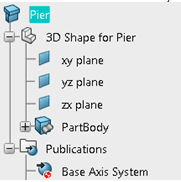
The 3D part or product is defined as a component with the required base axis system,
assembly features and publications. This is an example of what you can
obtain:

