Procedure for Designing an Adaptive Object Type

You can select among three types of object types. To design an adaptive object type certain elements are mandatory and other elements are optional. For maintenance purposes, design your user defined feature and your engineering template in the same numerical model

An adaptive object type must contain a user feature (feature-based design), an engineering template, and a medium icon. Optionally, it can contain a small icon, a documentation guide and a design table.

The stages in this procedure are as follows:

Create a Product Structure of your Model

You can either choose to create one product structure model to accommodate both the user feature and the engineering template or create separate product structure models for the user feature and the engineering template.

  1. Create a product structure model either:
    • A single product structure model to accommodate both the user feature and the engineering template or

      The changes are automatically reflected and updated in this single structure.
    • A separate product structure models for the user feature and the engineering template

  2. Create all the necessary elements.
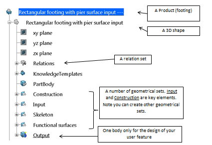
    The following example is a correct structure for the creation of the user feature.

Create a User Feature (feature- based design)

Creating a user feature involves selecting specific geometrical inputs around which your model should be built. You must create an axis system at a minimum and can also create other axis systems, surfaces, planes. You can add numerical parameters, Boolean parameters, list parameters to handle dimensions or for displaying certain portions of your model.

Note: Two key geometrical elements play a prominent role in the user feature:
  • Input axis
  • Input curve
For more information, see Manipulating input axis and input curve for designing user features.

  1. Create a user feature with a body as output.
  2. Open your Output body and select all elements.
  3. Right-click your selection in the tree, and select Insert In New in the context menu.
  4. Optional: From the Tools section of the action bar, click User Feature .
    The User Feature Definition dialog box appears.
  5. Enter the user feature name, and select the user feature inputs in the tree:
    1. Select the Relation set.
    2. Select the Construction geometrical set.
    3. Select the Functional surfaces geometrical set

      Do not select the geometrical set inputs (inputs tab)

  6. Optional: In the Input tab, rename the first input axis in Base Axis System. This is to comply with the storage rules for object information in civil engineering apps.
  7. For the other inputs, consider you instantiate the object type by using functional surfaces of another object type. Rename your inputs accordingly that is with the same naming.
  8. In the Meta Inputs tab, associate your inputs to the relevant objects. If the naming of the inputs of your object type is consistent with the naming of the semantic geometry of the instantiated object, you will only have to select the input object during instantiation.
  9. Publish all the parameters related to the definition of your object type
Create an engineering template (product- based design)

For your object design, you need to choose certain geometrical inputs around which your model should be built. You must create as a minimum an axis system but you can also create other axis systems, surfaces, planes, curves, points. You can define numerical parameters, Boolean parameters, list parameters to handle dimensions or to display certain parts of your model.

  1. Prepare your model and add geometry if necessary.
  2. Click Define Components to retrieve information at the product level (inputs, functional surfaces…).
    The Input axis is published automatically and named Base Axis System.
  3. Publish the remaining objects such as functional surfaces either with
    • Publication command
    • Semantic Geometry Tagger command
  4. Launch the Engineering Templates app.
    A new environment is open
  5. From the Compass, click Engineering Templates.
  6. In the Components tab, click your product (Footing in our example)
  7. Click the up arrow.
  8. Repeat the operation with the footing 3D Shape.
  9. Click your 3D shape in the
    The numerical model is displayed in the work area
  10. Click the Inputs tab.
  11. Click Add.
    The objects box lists all existing objects.
  12. Select the input objects in the object list, and click the right arrow.
  13. Rename the input axis in Base Axis System.
  14. In the Meta Inputs tab, associate your inputs to the relevant objects. If the naming of the inputs of your object type is consistent with the naming of the semantic geometry of the instantiated object, you will only have to select the input object during instantiation.
    Note: As a reminder, your footing is to be instantiated under a column. Click Add and rename your Meta Input in Column.
  15. Select all the geometrical inputs related to your column (Pier surface in our example), and click the up arrow.
  16. Click the Parameters tab, and click Add.
  17. Select each parameter in the left column and click the right arrow so that they are in the Selected object window.
  18. Click OK.
  19. Save the engineering template.

The engineering template is created.

Create a Thumbnail Icon

You must create a medium icon representing the object type to be displayed in the Search panel. Create the icon to associate it to the object type you are creating.

  1. Design the icon in pixel units.

    Leave an empty section at the bottom of the thumbnail. In this section, information on your object type will automatically be added.

  2. Save the thumbnail icon in .png format

Create Documentation Content

You can add documentation content to an object type.

  1. Write a reference document with detailed specifications and figures.
  2. Save the document to be associated to the object type.
    The supported formats are .doc, .pdf, .jpg

Create a Design table

You can create a design table for object types to limit the authorized configurations, such as specific dimensions for an object type (mostly manufactured items). Through the design table, you can specify manufactured configurations for your object.

  1. Create an Excel file with three specific sections to account for IFC parameters, parameters that are specific to the app, and object type parameters.
  2. Save the design table and reference in the resource table of the corresponding object type

Example of a Door Type Design table

In the component-based design approach, design tables can be helpful to enforce manufactured configurations. In this example, consider the door object type. A catalogue from a provider specifies the main dimensions of the door product. The various configurations are accounted for in the design table so that during instantiation of doors only the configurations defined in the design table are applied.

The naming of the parameters in the design table is related to the IFC4 standard (Industry Foundation Classes, it is a standard related to the usage and the naming of attributes). You can choose your own naming for your object types as long as it is consistent with the design table content. The table below show an example of design table.

Designation IfcDoor_OverallHeight IfcDoor_OverallWidth
door 2040*1500 2040mm 1500mm
door 2040*20002040mm 2000mm
door 2040*30002040mm 3000mm
Note: The naming of the parameters must be consistent between the exposed parameters of the user feature and the design table.