Automatic Configuration | ||
| ||
-
From the
View section of the
action bar,
click
Multi-View Customization...
 .
.
-
In the
Views and Layout dialog box, select the
Automatic tab.
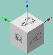
The six standard views are mapped onto a cube, each face of this cube being perpendicular to one of the directions of the 3D axis. Whatever the orientation of the cube, the observer can see three faces (that is, three standard views) as shown below:
The View Selection area represents the unfolded cube of standard views: each square represents a standard view and the square placed at the center is the base view around which adjacent views are automatically generated. In the default configuration displayed below, the base view is the standard Left View:

-
Select the standard view you want to define as the base view using one of these
two methods:
- Select directly in the View Selection area the view you want to define
as the base view: the selected view is at the center and all the adjacent
views are regenerated accordingly. In the example below, Back
View is selected:

- Click the translation arrow
 to shift Back View to the
center (or any other translation arrow depending on the standard view you
want to define as the base view). Clicking a translation arrow shifts the
views in the arrow's direction.
to shift Back View to the
center (or any other translation arrow depending on the standard view you
want to define as the base view). Clicking a translation arrow shifts the
views in the arrow's direction.
- Select directly in the View Selection area the view you want to define
as the base view: the selected view is at the center and all the adjacent
views are regenerated accordingly. In the example below, Back
View is selected:
-
Click
Apply.
The configuration is applied to the current tab and the Views and Layout dialog box stays open:
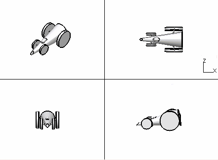
When you manipulate a viewpoint in one of the four views, the other three viewpoints are not modified and you can manipulate them independently from each other:
-
Select a group of views by clicking an
Isometric View in one of the four corners of
the View Selection area.
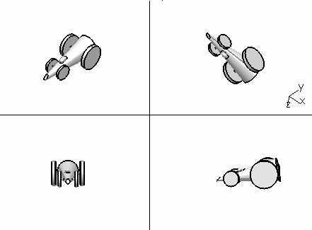
This amounts to selecting a vertex of the cube and you then see the three adjacent faces.
The selected Isometric View is computed from its three adjacent views and the four views (Isometric + adjacent) is highlighted: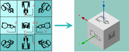
The View Selection area also contains four rotation arrows (such as
 ) enabling you to change the orientation of the
current base view: clicking an arrow rotates the base view by 90 degrees in
the arrow's direction. When the base view is rotated, all the adjacent views
as well as the isometric view are recalculated.
) enabling you to change the orientation of the
current base view: clicking an arrow rotates the base view by 90 degrees in
the arrow's direction. When the base view is rotated, all the adjacent views
as well as the isometric view are recalculated. -
Click the rotation arrow repeatedly and verify the result in the View Selection
area.
-
To go back to the standard view, click
Multi-View
 from the
View section of the
action bar.
from the
View section of the
action bar.