-
From the
View section of the
action bar,
click
Multi-View Customization...
 . .
-
In the
Views and Layout dialog box, select the
Standard Views tab.
The
standard views displayed in this dialog box are
identical to those available in the
View section of the
action bar.
-
Select the standard view you want to configure by clicking one of the icons
displayed to the left.
By default, Front View is selected. When another
standard view is selected, the preview displayed in the View Selection area is
updated.
-
Click
Apply.
-
Reselect Multi-View Customization....
The Views and Layout dialog box reopens and you can
see that the selected view (Back View in our example) is
still selected and we can now start customizing the view.
-
Use the four translation arrows (such as
 ) to shift the selected standard view by 90 degrees in the
arrow's direction. ) to shift the selected standard view by 90 degrees in the
arrow's direction.
Below is an example of the result you can obtain when clicking the translation
arrow repeatedly with Back View as the
selected view and starting position displayed to the left: 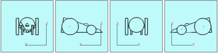
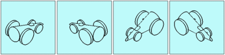
Note:
If the current standard view is an isometric view, the isometric view's
direction changes to one of the eight possible isometric views using
predetermined increments. Below is an example using repeatedly the right
translation arrow with the starting position displayed to the left:
-
Use the four rotation arrows (such as
 ) to change the orientation of the current view:
clicking an arrow rotates the view by 90 degrees in the arrow's direction. ) to change the orientation of the current view:
clicking an arrow rotates the view by 90 degrees in the arrow's direction.
Below is an example using repeatedly the rotation arrow with starting position displayed to the left: 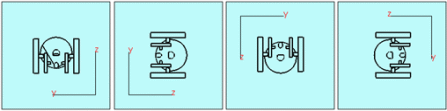
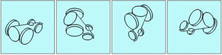
Note:
If the current standard view is an isometric view, the view is rotated by
60 degrees:
-
Use the three boxes displayed in the View Direction area to change
the direction of the current view.
This area indicates the direction of the selected standard view along the X, Y, and Z
axes (as shown below):
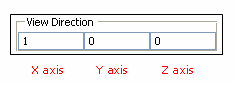
To change the direction, you can enter one of these three values in the
required box: -1, 0 or 1 before clicking Apply.
Note:
If the selected view is not an isometric view, you can enter a value only
in one of the three boxes: as soon as a value is entered in a box, the other
two are automatically filled with the value "0". On the contrary, if the
selected view is an isometric view, you can enter a value in the three
boxes. If you enter a positive value other than "1", it is changed to "1"
and if you enter a negative value other than "-1", it is changed to "-1".
For example, entering "-1" instead of "1" in the first box to the
left inverts the view direction along the X axis.
-
Use the Apply to axis area to position the selected standard view
according to the local axis or to the axis you select:
- When Use local axis is displayed, it means that the standard view is
positioned according to the active (that is, current) local axis. If no
local axis is active, the standard view is positioned according to the
global axis system (displayed in the lower-right corner of the screen)
of the UI-active object. For example, if a part is activated, the
standard view uses the part's axis as reference. To define an axis as
current, right-click it in the tree or in the 3D then select
xxx object > Set As Current.
- Selecting the
Select axis check box lets you position
the standard view according to a specific axis: to select the axis to be used,
first select the text
No Selection then click the axis to be
used in the 3D. The name of the selected axis is then displayed in the box.
The directions of the selected axis are saved in the CATSettings directory and are applied to
the standard view. This means that the standard view is always positioned
according to these directions and this, whatever the orientation changes you
might make afterward (for example, if you change the Robot orientation).
To apply new directions to the standard view, you need to select another axis. Note:
The
Select axis option remains activated even if
you select another standard view. Therefore, do not forget to deactivate
the option to be able to use the local axis. If your current axis system
is left-handed, the standard views are positioned according to the
global axis system.
-
When satisfied with your configuration, click
OK (or
Apply then
OK).
Your configuration is validated and the
Views and Layout dialog box is closed.
-
In the
View section, click the icon of the standard
view you have previously configured (Back View in our
example).
The modified standard view is applied to the current viewer.
|