Using Section Planes | |||
| |||
-
Add the Visualization Sectioning command to the action bar.
For more information, see Manage User-defined Sections from the Customize Dialog Box.
-
Close the Customize dialog box, and then click
Visualization Sectioning
 .
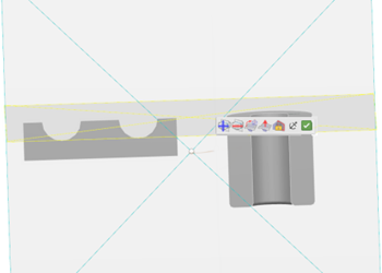
A context toolbar is displayed to let you customize the section visualization, a default section plane is created and selected with the Robot at its center:
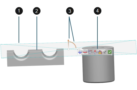
Notes (1) Section plane The section plane has a default color and transparency that cannot be modified. It cuts the entire geometry (the sectioning is infinite and global) but you can move its representation manually. Section results are automatically updated whenever an object is moved. The size of the section plane representation is fixed. Its size on screen automatically changes when you zoom in or out. But if you pan the camera, the section plane representation does not move.
The section plane's normal is parallel to the global Z axis. Additional section planes are created with a normal parallel to the global Y, X and Z axis, cyclically. The default section plane's position depends on the selection you made before running the command:
- If no object is selected, it is positioned at the center of the global bounding element of the work area.
- If objects are selected, it is positioned at the center of the bounding element of the selected object.
To select a section plane, click any of its edges: the color of edges changes from yellow to highlight color. The Robot appears only at the center of the selected section plane.
(2) Capping face Capping faces and contour (if any) are added to each element cut by a section plane, even though they are not covered by the visual representation of the section plane. They are always displayed when the Visualization Sectioning command is running and sections are activated. Visualization properties of capping faces cannot be modified, or picked.
Capping faces are displayed with a default color. The contour of the cap is not displayed and cannot be picked.
(3) Robot Lets you translate or rotate a section plane. (4) Context toolbar You can move context toolbar anywhere in the work area. To do so, point to the context toolbar and when the pointer changes to a cross with arrows, you can drag it to its new location.
-
In the context toolbar, click the appropriate icon to add or remove section planes.
Command Purpose 
Add Section Creates a new section plane. It is automatically selected. Notes:- If three section planes have already been created, the Add Section command is grayed. To create a new section plane, you must first remove one of the existing section planes before running the command.
- When adding a new section plane, its default normal depends on the default normal of the already existing section planes, regardless of the orientation changes you might have performed after their creation. This prevents any overlapping of the global axes by two section planes.

Remove Section Removes the selected section plane, the Robot and the capping faces. The elements cut by the removed section plane are restored. Warning: - This command works in object-action mode only.
- If all section planes are removed, all the commands of the context toolbar are grayed, except Add Section.
- When no section plane is selected, the Remove Section, Position Section, and View Normal to Section commands are grayed.
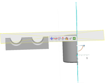
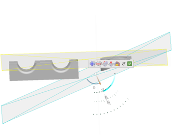
- To translate or rotate a section plane, use the Robot or the angle and length rulers.These rulers let you define precise values for positioning the section plane. You can either click the value displayed then enter the new value in the ruler field, or you can drag the arrow until you reach the appropriate value.
- Translation: you can either drag the arrow to move the section plane along its
normal, or use the angle ruler. Note that you cannot translate the section plane
perpendicular to its normal.

- Rotation: you can either drag the two arcs to change the orientation of the section
plane, or use the length ruler. Note that you cannot rotate the section plane about
its normal.

- Flip normal: click the translation arrow to flip the section plane's normal.
- Translation: you can either drag the arrow to move the section plane along its
normal, or use the angle ruler. Note that you cannot translate the section plane
perpendicular to its normal.
-
Drag the handle, and then drop it onto the geometry element of your choice to snap the
section plane to geometry.
The section plane's position depends on the type of geometry to which it is snapped:
- Planar face: the section plane is positioned at the snap point on the planar face with its normal parallel to the face's normal.
- Conical or cylindrical face: the section plane is positioned at the snap point on the face's axis with its normal perpendicular to the axis.
- Straight edge: the section plane is positioned at the snap point on the edge with its normal along the edge.
- Curved edge: the section plane is positioned at the snap point on the edge with its normal along the tangent to the edge.
- Vertex: the section plane is positioned at the snap point with its default normal orientation.
- Background: when dragged to the background, the section plane is snapped back to its previous position.
-
To change the position of a section plane, use the Position Section command:
Purpose Action 
Position Section Click any of the section plane's edges to make it active (the section plane itself is not pickable), select Position Section then choose the appropriate command.
Important: - You cannot select multiple section planes at the same time.
- The section plane position and orientation are independent of the geometry: if an object is moved, the section plane does not move.

Orient Section to X axis Makes the section plane normal parallel to the global X axis. 
Orient Section to Y axis Makes the section plane normal parallel to the global Y axis. 
Orient Section to Z axis Make the section plane normal parallel to the global Z axis. 
Position Section on Selected Geometry Sets the position and orientation of the section plane according to the geometry elements you select: - Three points: the section plane is positioned on the plane formed by the points. The selected points must not be collinear.
- A line and a point: the section plane is positioned on the point with its normal parallel to the line. The selected line and point must not be collinear.
- Two points and a line: the section plane is positioned on the plane formed by the two points and the line. The selected points and line must not be collinear and must be coplanar.
- Two coplanar lines: the section plane is positioned on the plane formed by the lines. The selected lines must not be collinear.
- A line and a plane: the section plane is positioned on the line with its normal parallel to the plane's normal. The selected plane must be parallel to the line.
- A plane: the section plane is positioned on this plane.
- To move the section plane, you can also use the following commands:
Purpose Action 
View Normal to Section Positions the object perpendicular to the selected section plane. 
Enable Automatic Snapping Prevents the section plane from moving with the geometry when panning, rotating, or zooming. The position is dynamically updated to keep the handle origin at the view center.

Disable Automatic Snapping Moves the section plane with the geometry when performing viewing operations. This capability is especially useful to keep the section plane's rotation center fixed to the snap point on geometry.
- To manage section results, click Deactivate Sections.
 Inversely, click Activate Sections
 to restore all the section results.
Deactivate Sections Activate Sections 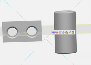
The Deactivate Sectionsand Activate Sections commands are also available from the context menu when the Validate Sections command has been run.
Tip: Section planes are not impacted by the Hide/Show command. Elements cut by section planes remain cut whether they are displayed in the Show space or in the No Show space. The section planes, the Robot, the cut elements as well as the context toolbar are displayed when swapping to the No Show space. - Click Validate Sections
 to confirm the section results.This makes the section planes, the Robot and the context toolbar disappear. The section results are shown if the sections have been activated, or they are hidden if the sections have been deactivated.
- Optional: When sections are validated, right-click anywhere in the work area then select Visualization Sectioning > Restore All Sections to bring back the section planes, the Robot and the context toolbar.
To change only the state of the section results, right-click anywhere in the work area, and then select Visualization Sectioning > Deactivate All Sections (if sections results have been activated before the validation) or Visualization Sectioning > Activate All Sections (if sections results have been deactivated before the validation).
-
To exit the command, click Visualization Sectioning
 .
.