Use the Object Properties Panel
You can display and edit the graphic properties (color, transparency, line type and thickness, etc.) of a selected object. The values you set in this panel are kept from one app to another in the same session.
- The default values of the Object Properties panel are stored in preferences files (which are identified by the suffix *.CATPreferences and cannot be administered). This means that default values are kept throughout sessions.
- This scenario only details options common to all apps. For additional elements that might be displayed, see the guide of interest.
- The Object Properties panel is immersive which means that you can perform layout modifications.
- To access the
Object
Properties
panel, do one of the following:
- From the
Tools section of the action bar, click
Object Properties
 .
. - Right-click inside the work area or the top bar, and select Display > Object Properties.
- From the
Tools section of the action bar, click
Object Properties
- Click the arrow next to Graphic Properties.
-
Use the appropriate list or icon to define the graphic properties of the
selected element:

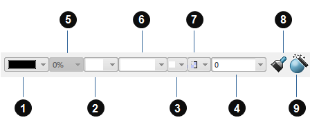
List/Icon Purpose (1) Color Lets you select the color to be applied to the object. If a line or a curve is selected, you can change the color the same way as for parts.
Note: The No Color option is relevant for Assembly objects only and lets you apply a color onto a face without having to modify the product color. To do so:- Select the product in the tree.
- Choose No Color in the Color list.
- Select the face onto which you want to apply the color.
- Select the desired color from the Color list.
The Properties dialog box modifies the color of the selected object whereas the Object Properties panel may sometimes modify the color of a non-selected object to make the color displayed on screen change.
(2) Thickness Lets you define the line weight. If a line or a curve is selected, you can change the thickness the same way as for parts.
(3) Point symbol Lets you set the symbol to be used to represent points. (4) Layers Lets you assign the selected objects to a layer. When pointing at the Layers list, a tooltip displays the layer name (if any), the layer number as well as the storage location of the layer definition.
(5) Opacity Lets you define the object's visibility: "100%" corresponds to a full visibility, "50%" to a semi-transparency and "0%" to a non-transparency (the object is opaque). When setting an Assembly object as transparent, any other element located at a lower level in the tree inherits this opacity and the list displays the visibility of the Assembly object. However, the opacity modification impacts only the display at rendering level and not the graphic properties. This can be useful to make an object transparent without altering its graphic properties.
To deactivate the inheritance mechanism, select an element then click the Opacity list and choose No Opacity: all the elements located at a lower level have their own transparency back.
Note that the visual feedback differs according to the transparency mode you set in Me
 > Preferences
General > Display >
Performance.
 Important: The opacity you set on an Assembly object modifies its visibility. Therefore, the Graphic Properties Wizard and the Object Properties panel give you the visualized property of the sub-element (inherited from the Assembly object) but when you access the graphic properties of the sub-element itself, you can see its true properties. (6) Linetype Lets you define the edge line type (dashed, etc.). If a line or a curve is selected, you can change the line type the same way as for parts.
(7) Rendering style Lets you select the style to be used to render the selected object, provided that it supports rendering styles. This option is identical to the one provided in the Properties dialog box.
(8) Painter 
Lets you apply graphic properties from one object to another. To do so:
- Select the objects on which you want to apply new graphic properties.
- Click
 to start the Painter.
 - Select the reference object (i.e. the object from which you copy the graphic properties): the graphic properties of the objects selected in the first step are applied to the reference object.
Important: The Painter does not allow you to copy all the graphic properties of an object, but only a set of graphic properties for each list. For example, you cannot modify the color of edges and faces of a part body at the same time but only the color of faces. The reason is that the Painter has the same effect as the lists displayed in the Object Properties panel: when you use the Color list, you modify only the color of faces. Therefore, when you use the Painter to modify a color, only the color of faces is impacted. (9) Wizard 
Lets you access the Graphic Properties Wizard.