Selecting Objects

You can use the mouse to select objects either by dragging a bounding outline, or through the different trap selection modes provided. When no command is running, the Select command is active and all the selection tools are available.

This task shows you how to:


Before you begin: When objects are selected through the Select command, a context menu named xxx object (when one object is selected) or Selected objects (when multiple objects are selected) is available. However, only generic commands are displayed in this context menu if more than 50 objects are selected. To display the whole menu, increase the value of the Limit display of handles to ... element(s) option through Me > Preferences > General > Display > Navigation. Note that increasing the value has an impact on performance and the display of the context menu might be delayed.

Select with the Pointer

You can use basic selection techniques with the pointer to highlight and select objects in the tree and in the 3D area.

  1. To access the App Options panel, do one of the following:
    • From the Tools section of the action bar, click App Options .
    • Right-click inside the work area or the top bar, and select Display > App Options.
  2. From the App Options panel, click Select to enter selection mode.
  3. Point to the part of the object you want to select. You can select the constituent elements of objects (faces, vertices, edges, planes, axes).
    As you point to objects, different parts of the objects are highlighted in the 3D area, and the object name is highlighted in the tree. If View > Status Bar has been selected, the preselected element is also identified in the status bar.

    On certain objects, hidden faces and edges are also highlighted as you point at them and are displayed in a different color.

    Important:
    • Highlighting is active only if the Preselect in geometry view option is activated in Me > Preferences > 2D 3D View Display > Visualization.
    • In the case of overlapped elements, arrows are displayed to indicate to which element the edge belongs to. The display of highlighted edges has priority on the display of other elements of the geometry. But if you select a global element of the geometry such as the product or the part body, the highlighted hidden edges are not displayed.
  4. Click the element to select it.
  5. Hold down Ctrl and select another element.
    The selected element is added to the initial selection.
  6. To cancel the selection, press Ctrl + click the element you want to clear from the selection.
  7. Press Esc or click anywhere in the 3D area to cancel the selection of all the selected elements.
Select with the Bounding Outline

You can use your mouse to drag a bounding outline and select the objects it contains.

  1. From the App Options panel, click Select to enter selection mode.

    To access the App Options panel, from the Tools section of the action bar, select App Options .

  2. Left-click + drag.
    A bounding outline appears as you drag.
  3. Drag the bounding outline until the objects you want to select are completely inside the bounding outline.

    The objects must be completely inside the bounding outline: if not, they are not be selected.

  4. Release the mouse.

The objects are highlighted to indicate that they have been selected.

Select with the Selection Traps

When working in different apps, you can use a different trap selection mode for each app. However, if you open multiple tabs for a same document in an app, the trap selection mode is the same for all tabs.

Before you begin: Selection traps do not allow you to select subelements (such as edges, faces, or vertices).
  1. To access the App Options panel, from the Tools section of the action bar, select App Options .
  2. From the Select area, click the selection trap of your choice.

    By default, Rectangle Selection Trap is active but it is deactivated as soon as you select another mode because only one mode at a time can be active. The icon of the chosen selection mode replaces the Select icon to indicate that this mode is active.

    Whatever the selection mode, you can keep on selecting objects if the selection mode is active, you do not need to click its icon before each selection. This is why the icon of the trap mode you select and the Select icon are both activated in the flyout.

  3. Drag the trap.

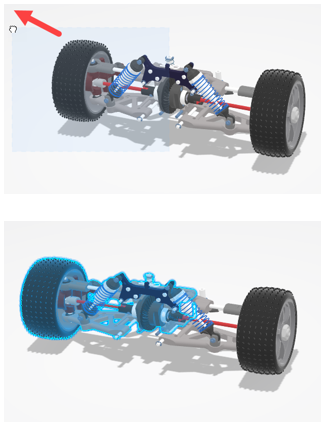
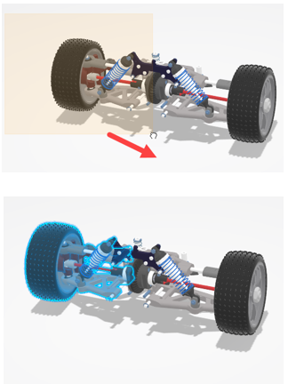
    In Dual Method Selection Trap mode, the way the trap is drawn has an impact on the resulting selection and the trap color changes accordingly:

    Trap drawn from left to right Trap drawn from right to left


    Important: When Polygon Selection Trap is active:
    • Each click you make is identified by a new point of the polygonal trap. However, if this mode is active, the mouse clicks are not received by the current command, which means that:
      • In the Select command, you cannot empty your selection by clicking an empty space.
      • In Sketcher commands, you cannot draw sketch elements.
    • The following visualization commands are deactivated as soon as you start dragging the trap: Full Screen, Perspective, Parallel, Fit All In, Rotate, Normal View, Multi-View as well as the standard views.

    To cancel the selection for an object, press Esc twice.

  4. Release the mouse.

The objects are highlighted to indicate that they have been selected.

Note: Regarding point intersection in Outside Intersecting Rectangle Selection Trap mode, only point symbols whose middle point is located inside the trap are selected:
Point is not selected Point is selected