- From the Review section of the action bar, click Fiber Direction
 . .
- Select a ply.
No producibility feature is required for the selected ply. - Pick a point inside the ply boundaries.
- Select an existing point, lying on the ply
shell and inside the ply boundaries.
- Or pick a nonexisting point.
- Select Theoretical fiber orientations.
The long and blue solid axis corresponds to the primary fiber direction, and the short
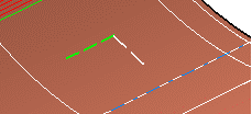
and red solid axis to the 90 degrees off angle. 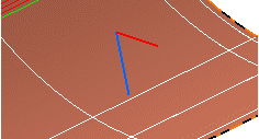 - Select Rosette transfer.
The green dotted axis corresponds to the X-axis of
the rosette, and the white dotted axis to the Y-axis.
 - Select both options.
For a bi-directional material 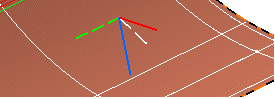 For an uni-directional material, only the X-axis is displayed. 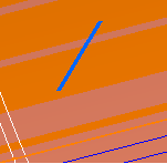 - Click Keep
to create the lines corresponding to the displayed axes.
- Select the Automatically aggregate geometry under selected ply check box to create the datum lines under the ply.
- Datum lines corresponding to the Theoretical fiber orientations
axes or the Rosette transfer axes are created in the current
In Work Object.
- If the check box Automatically aggregate geometry under selected ply is selected, the datum lines are created under the ply. Otherwise, they are created under the In Work Object.
- If the current In Work Object is not a geometrical set, or is a Composites
body, they are created in a new geometrical set.
- They have the same colors and dimensions as displayed.
|