About Iso-Thickness Areas

Below is some information about iso-thickness areas.

This page discusses:

General Information

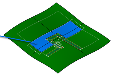
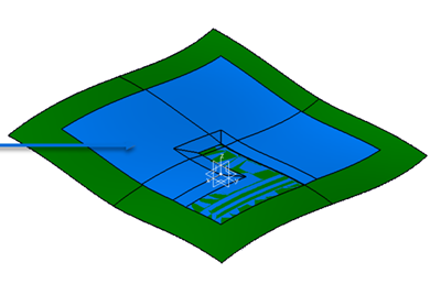
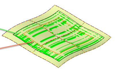
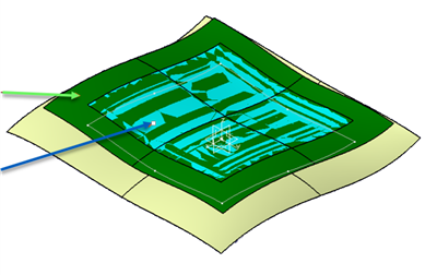
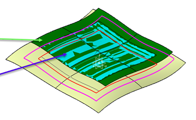
An iso-thickness area is an area of the reference surface

An iso-thickness area

  • Shares a common thickness (given by the stacking in this area).
  • Is continuous and manifold.
  • Has been relimited at each edge corresponding to a bottom slope.

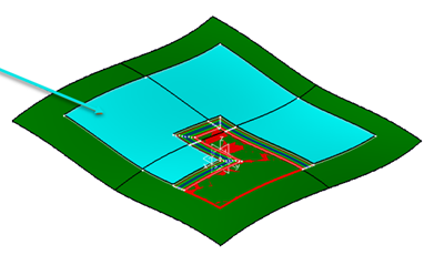
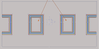
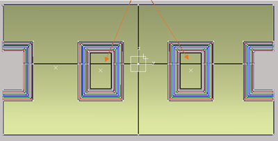
Iso-thickness areas used to generate the solid or the top surface are grouped together in an iso-thickness areas group. The selection of iso-thickness areas in group, their relimitation/completion, and the way they are connected have a strong impact on the final solid or top surface.

Once the plies have been generated as required,

  • For one or several plies groups, you can:
    • Perform an automatic initialization of the iso-thickness areas to select.
    • Modify or complete manually the iso-thickness areas of the group.
  • For each iso-thickness area, you can:
    • Generate a shell (resulting geometry).
    • Generate an offset surface.
    • Generate shell boundaries.

You can use Iso-Thickness Areas

  • To create iso-thickness areas. An iso-thickness areas group is automatically created.
  • To edit an existing iso-thickness areas group. In edition mode, some controls of the dialog box are not active.

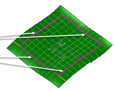
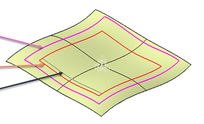
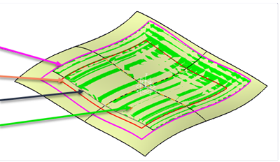
Area limits and extended limits options are proposed, and can be combined.

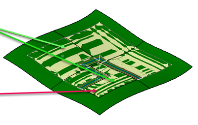
Once created, iso-thickness areas are editable on their own.

Area Limits to Consider

You can limit the ITA by a contour or a Composites geometry.

Two options are proposed:

  • Iso-Thickness Area, with a contour or a geometry.
  • No Thickness Area, with a contour or a geometry, or automatic computation: Areas without plies inside the limit are included in the ITA group, as ITA with no thickness (0.001mm) and in the top surface.
    Note: No Thickness Area is taken into consideration when creating a top surface, not when creating a solid.

Iso-Thickness Area

Use this option to create a top surface on a specific area of a large panel: ITAs are created only inside a selected contour or Composites geometry lying on the support surface of the stacking. In this example, the ply boundary is shown by the orange arrow, the selected Iso-thickness area contour by the pink arrow, and the ITA group by the green arrow.

The top surface is shown in blue.

No Thickness Area with Contour

  • In our example, the top surface is shown in blue. The No Thickness Area is the red color one.

  • Create a contour from reference elements (shown by white arrows) and select it as No Thickness Area.

  • The ITA group is created using the No Thickness Area contour.

    The ITA group is shown by the green arrows. The No Thickness Iso-Shell is shown by the red arrow.

    Resulting in the following top surface (in blue).

No Thickness Area Auto

  • In this example, the arrows show holes.

  • The contour is automatically computed, resulting in

Extended Limits

Extended limits, defined by user or automatically computed, are to compute extended ITA group, from which an extended top surface or solid can be generated.

Since we recommend not to use the reference surface boundary to create plies, the top surface below (blue) is not appropriate to create plies. It also does not have sufficient material excess for manufacturing preparation.

Auto with Offset Value

  • In the example below, we have extended the ITA by an offset value of 30 mm.

    The extended ITA group is shown in green, the plies boundary in orange.

  • The ITA group can be used to create an extended top surface, used as reference surface for the next level of plies design.
    • The original top surface is shown in blue.
    • The extended top surface is shown in green.


User Defined with Extended Limit and Start EOP

Use this option to extend more in a specific direction, or if no thickness areas exist.

  • In this example, the Extended limit is shown by the pink arrow, the Start EOP by the orange arrow and the plies boundary by the black arrow.

  • Since Start EOP coincide with plies on 3 sides, the ITA is extended in 3 directions.
    Note: Extended limit and Start EOP can be curves parallel to reference elements or ramp support curves.
  • The resulting extended ITA group is shown by the green arrow.

  • The extended top surface is shown by the green arrow, the original top surface by the blue arrow.

Notes:
  • All plies must be inside the Start EOP.
  • Extended limit must be larger than Start EOP.

Solving Problems

You may encounter some problems while creating iso-thickness areas.

Below are some possible solutions.

ProblemHighlight in 3D areaPossible solution
There is no solution for this operation.NoneNone
Minimum width for ITA selection must be greater than 0.NoneModify the value.
Maximum and Default Drop-Off Values must be greater than 0.NoneModify the values.
Maximum Drop-Off Value must be greater or equal to Default one.NoneModify the values.
Some plies have no material defined or a null thickness.NoneVerify the material definition of the plies.
Some plies do not have the same draping direction, or do not share the same support surface as the reference plies group.NoneVerify the surface definition of the plies.
The selection of the area location failed, the point may lay outside the Composites part.NoneMove the point inside a ply shell.
The selection of disconnected faces failed, the input point may lay on a ply contour.NoneMove the point, or select a more centered one.
The relimitation of the iso-thickness shell by the bottom of slope leads to an unexpected result."Non-relimited edge" displayed on those edgesVerify the input point, plies and relimit the shell manually.
The relimitation of the iso-thickness shell by bottom curves leads to unexpected result. The input point would probably be outside the resulting shell once relimited by bottom of slopes."Non-relimited edge" displayed on those edgesVerify the position of the input point.
The iso-thickness areas are identical."Duplicated iso-thickness areas"Remove the duplicate area, or verify the ply definition.
The iso-thickness areas are connected to each other."Connected iso-thickness areas"Verify the ply definition.
The iso-thickness areas are overlapping."Overlapping iso-thickness areas"Verify the ply definition.
A No Thickness Area is created next to an area with plies, with no stagger between them.WarningSelect another contour or Composites geometry.