About Composites Design Import | ||
| ||
The proposed formats are:
- Default format with plies group column with
the following template:
Plies Group Sequence Ply Material Orientation Starting Plane End Plane LEFT LIMIT Offset RIGHT LIMIT Offset 2 - Default format without plies group column with
the following template:
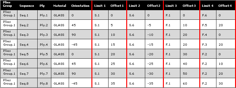
Sequence Ply Material Orientation Starting Plane End Plane LEFT LIMIT Offset RIGHT LIMIT Offset 2 - Long skinny part format (4 limits & 4
offsets) with the following template
Plies Group Sequence Ply Material Orientation Limit 1 Offset 1 Limit 2 Offset 2 Limit 3 Offset 3 Limit 4 Offset 4
Default Format with or without Plies Group Column
Both formats require a reference plane.
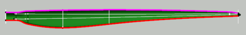
For example, the data found in this spreadsheet

are used to create the grid reference elements, taking the
reference plane into account. In the images below:
- 1 is the reference plane.
- 2 is the starting plane. 2000 is its distance to the reference plane (smaller double-headed arrow).
- 3 is the end plane. 4000 is its distance to the reference plane (longer double-headed arrow).
- The left limit is shown in pink.
- The right limit is shown in red.

Other required inputs are:
- The Grid panel.
- The Ramp supports step.
- The Construction Inputs such as the Parallel type and Parallel mode. See Specifying a Ramp Definition for more information.
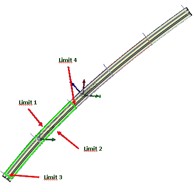
Long Skinny Part Format (Limits and Offsets)
For the following data
import requires:
- The Grid panel that contains the Reference Elements (S.1...S.6, F.1...F.6) to create the grid reference elements.
- The Ramp supports step.
- The Construction Inputs such as the Parallel type and Parallel mode. See Specifying a Ramp Definition for more information.
Note:
The
Ramp supports step is the default step used to
create all the automatic ramp supports. If the offset values are not a multiple
of this step, the import stops.
- Either edit the offset values that are not a multiple in the spreadsheet and restart import.
- Or continue and switch all the ramp supports with a value that is not a multiple of the step
from automatic to custom.
- The parallels are created in a new geometrical set.
- The custom ramp supports are created using the parallels.
For example, let us consider the creation of Ply.4 with an initial Ramp supports step of 10.
- Create Limit 1: S.1 with Offset=15
- 15 is not a multiple of 10.
- A Custom Curve is created and aggregated to the Grid Ramp Support associated to S.1
- Create Limit 2: S.6 with Offset=-15
- 15 is not a multiple of 10.
- A Custom Curve is created and aggregated to the Grid Ramp Support associated to S.6
- Create Limit 3: F.1 with Offset=-20
- 20 is a multiple of 10.
- A Parallel is created and aggregated to the Parallel/Parallel Grid Ramp Support associated to F.1
- Create Limit 4: F.3 with Offset=-20
- 20 is a multiple of 10.
- A Parallel is created and aggregated to the Parallel/Parallel Grid Ramp Support associated to F.3
- Create the contour of the ply from the 4 curves.
- Create the sequence and the ply with GLASS as material, -45 as orientation and the above contour.