About Plies Creation from Virtual Stacking | ||
| ||
General Information
- The contour of the plies are based on the sequence shapes (cell coverage) and on the initial staggering defined on structural elements during the panel creation. If the staggering value is 0, a warning message is issued.
- Drop-offs are optimized directly for each group of plies with the same shape, and a pattern is applied depending on that shape.
- A ramp support is a section of the structural element from which a group of plies drops off.
- Ramp supports are automatically computed. However they can be edited.
- The definition of the limitation side of limit contours is taken into account.
- If you generate a second plies group from a virtual stacking that already contains a plies group, only the plies group created first is synchronized with the virtual stacking (the second one is not synchronized).
Plies are generated as follows:
- Ramp supports are grouped by structural elements groups and by side.
- The stacking is generated with ply contours based on the ramp entity curves.
- To reduce the number of useless ramp support curves, one ramp support is created for each structural element per side (+1 and/or-1).
If a plies group has already been generated from the selected virtual stacking, you are prompted to update it. New and temporary plies are generated in a plies group. These new temporary plies and plies group are compared to the existing, that are then updated as follows.
- You must have switched to upgraded rosette mode.
- Surface, lay-up direction, and rosette of the plies group must be the same as for the grid panel of the virtual stacking.
- If the ply group had been defined with layer levels, and if some layer levels are now missing, update is impossible.
- The names of the virtual plies and virtual sequences in the virtual stacking must be unique.
- There cannot be a mix of plies and cores inside the same sequence.
- Ramp support fallback strategies are not stored in the plies group. They are retrieved from the parameters defined in Plies From Virtual Stacking.
- If required, the old plies group is migrated to automatic shells mode.
- If a ply of the old plies group is not in the newly generated plies, it is deleted.
- Empty sequences are deleted.
- If a newly generated ply is not in the old plies group, it is added. The corresponding sequence is created too if needed.
- Sequences are renamed if needed.
- All modifications of the plies attributes are carried over to existing plies.
- For each ply, new contours are compared to old ones:
- In most cases, plies have a single contour. If the old and new contours have a similar
definition, the old one remains unchanged. Otherwise, it is updated from the new
input list.
Two contours may have a different but similar definition: They have the same input curves but in reverse order.
- When a ply has several contours, they are compared in their order in list. Extra contours are added, missing ones are removed.
Notes:- Only first standard contours are analyzed, others (limit contours, rounded corners, material addition, material excess, ...) are ignored.
- If the contour inputs are modified, the contour is upgraded.
- In most cases, plies have a single contour. If the old and new contours have a similar
definition, the old one remains unchanged. Otherwise, it is updated from the new
input list.
- If a newly generated ply is located in a different sequence, because the cell covering has changed, the existing ply is moved accordingly.
- If required, plies are re in existing sequences and existing sequences areordered re in the plies group to match the temporary plies group.
Case of Staggering or Weight Saving Steps
Let us consider the following example:
- Cell gauges areordered as follows

with the following staggering defined for vertical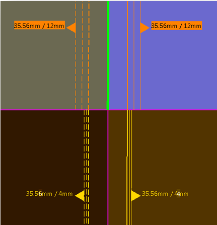
and horizontal structure reference elements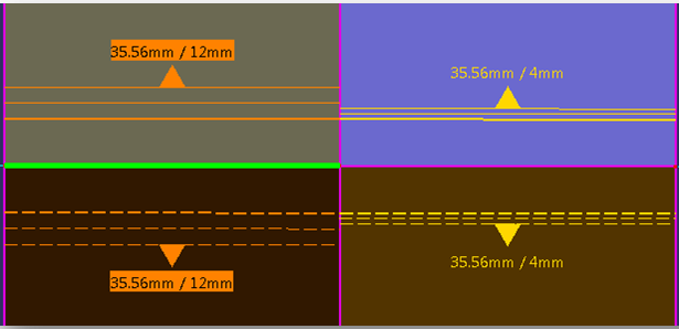
- Plies are generated as follows:
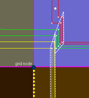
In a detailed view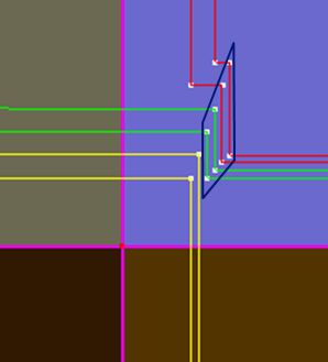
steps appear in the ply shapes because of staggering change on the horizontal structure reference element.Note: They could also appear for weight saving reason. - The staggering definition used for these steps is that of the yellow plies. It is the
staggering definition below the grid node on the vertical structure reference element.
This ensures a constant ramp in the white dotted line region.
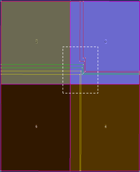
Let us consider another example with different cell gauges and the same staggering definitions as
previously: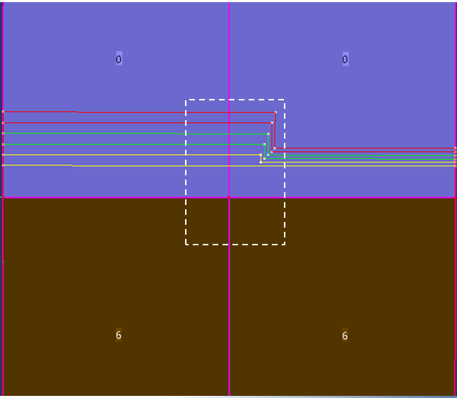
resulting in 
Although there are no ply drops between the cells below the node, the staggering step uses
the staggering definition below the grid node on the vertical surface reference element
(same as in the previous example):
- As a designer, you might have used the staggering definition above the grid node for the step.
- However, to be consistent with the first example, and with all cases, the chosen algorithm is that of the first example.