Creating a Butt Splice Zone | ||
| ||
A Butt Splice Zones group is created under the Stacking, if it does not already exist, and the Butt Splice Zone is created in that group.
Notes:
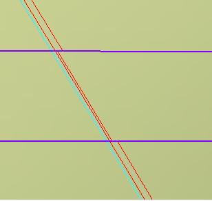
- If the number of intersections between the splicing curve and the zone is not equal to the number of intersections between the overlap curve (parallel to the splicing curve) and the zone, the butt-splice curve cannot be defined.
- If you create splice plies, this is what you obtain: Within the Butt Splice
Zone, the cut-pieces do not overlap, and there is a small gap between
them.

- Butt Splice Zones are taken into account by Skin Swapping if you select the Stacking node.
- If the Skin Swapping was applied to elements under the stacking, you can generate a Skin Swapping feature for the Butt Splice Zones by selecting either a zone or its group. In this case, a Skin Swapping feature is added at the end of the Composites Geometry of the corresponding elements.

