-
From the
Plies Design section of the
action bar,
click
Core
 . .
-
Select the stacking.
-
Select a solid as the
Geometry.
-
Select the material, a direction, and a rosette.
Direction and Rosette orientate
the insert cells. See About Rosette and Rosette Transfer Type
for more information.
A new sequence is created at the end of the Stacking.
It contains the core and its definition.
-
To create a variable core, press
Variable Offset Core Definition
 . .
-
Press
 to define
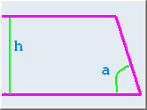
a variable core from a contour, height, and angle. to define
a variable core from a contour, height, and angle.

-
Select the
Base Contour.
-
Key in a
Height (h).
-
Key in an
Angle (a).
-
Alternatively, press
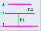
 to define a variable core from contours and heights. to define a variable core from contours and heights.

-
Select the base contour (shown as 1). As it is the base
contour, leave its
Height to 0.
-
Select the second contour (shown as 2) and its height (h1).
-
Repeat with the third contour (shown as 3) and its height
(h2).
-
If required, add junction lines.
-
Click
Edit Junction Lines.
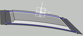
In the 3D area, potential junction lines are displayed. A red traffic light is
displayed at the start of the current contour. It turns green when
all junction lines have been proposed for all vertices.
-
Click the green traffic light to validate all proposed
junction lines.
-
Click the red traffic light to reset the definition of
junction lines.
-
Click the red marker of a junction line in the 3D area to delete one given junction line.
-
Click the red marker of a junction line in the 3D area to delete one given junction line.
-
To create a variable core from contours and heights with a 90°
wall, proceed as explained above, but select the same contour twice.

- The
Variable Core is created after the
Stacking, under
Solid:CoreGeometry.
- The Solid:CoreGeometry is hidden, only the
Core is visible in the 3D area. This ensures a correct computation of the
inertia, without having to manually hide the Variable
core
- The
Variable Core can be edited from
Variable Core in the
Core dialog box, the
Core been updated accordingly.
- When a Core is created from a PartBody as
Geometry (Pad), the representation of the
Core is created while the PartBody is hidden.
- When a
Core is created from
Solid:CoreGeometry as
Geometry, the representation of the
Core is created
whileSolid:CoreGeometry is hidden.
|
 to define
a variable core from a contour, height, and angle.
 to define a variable core from contours and heights.


