Select Entities
You can select the entities to flatten.
-
From the Producibility, Flattening and Splicing section of the
action bar, click Flattening
 . .
-
Select a ply, a ply sequence, a plies group or a stacking.
- The numbers of plies and cut-pieces are computed and displayed in the dialog
box.
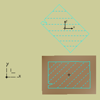
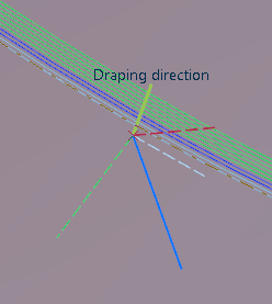
- Axes appear on the ply seed point on the surface, where:
- The blue axis is the main fiber orientation of the ply.
- The red dotted axis forms a 90° angle with the main fiber orientation of the
ply.
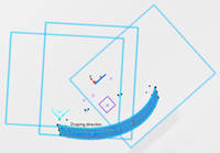
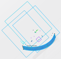
- The yellow axis is the draping direction of the ply (if the
Transfer draping direction to plane normal check box is
selected).
- If the main fiber orientation of the ply is different from 0°, the X-axis and
Y-axis of the transferred rosette are shown too.
-
Select or clear Only consider cut-pieces to determine where
Flattening nodes are created.
When they exist, cut-pieces are created under a cut-piece group
under the ply.
- When Only consider cut-pieces is selected:
- If the ply has an associated cut-piece group, the
Flattening nodes are created under the cut-piece group,
under the cut-pieces (one Flattening node per cut-piece).
No Flattening node is created under the ply.
- If the ply has no associated cut-piece group (thus no associated cut-piece),
the Flattening node is created under the ply (one
Flattening node per ply).
- When Only consider cut-pieces is cleared,
Flattening nodes are created under all the plies and all
the cut-pieces (one flattening per ply and one per cut-piece).
Create Location Points
You can use several methods to select the location points.
-
Select a plane as the flattening support.
- You can reference an existing plane under a plies group. As a consequence, the
plane box is already filled when you start Flattening and all
created flatten curves lie on this plane.
- Should you need to create the plane or the location point, right-click the
appropriate box and create the element you need.
- Its name is displayed under Plane.
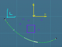
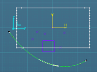
- Axes appear at the center of the plane or at the flatten origin, where:
- The white axes are the X-axis and Y-axis of the plane.
- The blue axis is the 0° fiber direction of the flatten shape.
- The red dotted axis forms a 90° angle with the main fiber orientation (red
axis) of the flatten shape.
-
Select the location points.
- Pick one single point in the work area.
- Click
 to
select several points. to
select several points.
- Right-click Location Point to create them.
- Select a geometrical set containing points.
- Select a pattern of points. This is a quick way to position the
flattenings.
- Each point or vertex (for patterns) is automatically assigned to a ply or a
cut-piece.
- If there are more plies or cut-pieces than points, the plies without location
point use the center of the flatten plane as location point.
Use the Location Points Creation Wizard
You can use the Location Points Creation Wizard as an
alternative.
-
Open the Location Points Creation Wizard
 . .
-
Verify the number of plies and cut-pieces. Their sum determines the number of
location points to create.
-
Select or create the reference point from the context menu.
All other points are computed from this reference.
-
Optional: Click the proposed axis to invert the orientation.
-
Key in the Number of Flattens per Row.
-
Key in the Minimum Clearance Value.
The distance between points is computed as (Current ply size+Next ply
size)/2+Minimum clearance value
-
Select an option to create a pattern.
- Create Rectangular Pattern.
- Equidistant Pattern: Creates a grid of equidistant
points, equivalent to a rectangular grid, from the reference point and the
Number of Flattens per Row.
- Space Optimized Pattern: Optimizes the creation of
points, useful where there are large differences in the plies sizes.
- Gather Cut-pieces of same ply in a row: Points associated
with cut-pieces of the same plies are in the same row. This way, you have a clear
view of the flatten bodies of plies and their cut-pieces.
- If plies have no cut-pieces, only flattenings of plies are shown.
- If Only consider cut-pieces is selected, plies
corresponding to cut-pieces are not taken into account to compute points.
- If Only consider cut-pieces is cleared, cut-pieces and
their parent ply are in one row.
-
Click OK in the wizard.
The number of location points is displayed in the main dialog
box.
Specify More Flatten Options
-
Optional: Select the Transfer draping direction to plane
normal check box.
-
Select a Flatten type and click Apply
to visualize the flatten shapes.
-
Optional: Select the Create Flatten as Sketch
check box to associate the flatten curves to the plies.
- If Create Flatten as Sketch is not selected, the flatten
curves of a given ply (contour and rosette) are created as a closed contour on the plane around the location
point, without any associativity with the ply.

- When Create Flatten as Sketch is selected:
- The flatten contour and rosette are projected onto the positioned
sketches.
- For a given ply, two positioned sketches are created

- One for the rosette
- One for the flatten contour
They lie on the plane. Their origin is the location point for producibility. They are oriented along the X-axis
of the rosette.
- Double-click to edit the positioned sketches. Edited positioned sketches are
marked with an update icon.
-
Double-click the Flattening node to re
Flattening and update the Flattening
result.
-
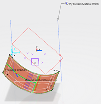
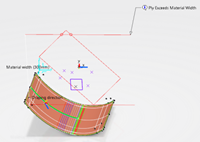
Optional: Select the Check material width check
box, and click Apply.
The control is done as follows:
- Two lines representing the material roll sides are displayed on the flatten
shapes.
- The first line is positioned at the extremity of the flatten shape.
- If the second line intersects the flatten shape, a warning is displayed but does
not prevent the creation of the flatten shape.
- If the flatten shape is larger than twice the material roll width, additional
lines are displayed.
- With Along warp: The lines are perpendicular to the blue
line of the transferred rosette
- With Along weft: The lines are perpendicular to the red
line of the transferred rosette.
- Switching from one option to the other rotates the lines by 90 degrees.
Diagnoses are displayed in the work area. In addition, a red or green sign appears in the
dialog box to indicate if the flatten shape fits into the material roll width (green
mark) or not (red mark).
-
Select the size of the flatten rosette.
This is useful when the size of the flatten geometry makes it
difficult to visualize the rosette.
Simplify the Geometry
-
Under Smoothing, to define how to simplify the flatten
geometry, select Threshold from the list and define the related
parameters.
- No Smoothing
- Threshold takes the tangency and curvature threshold into
account.
- Point ensures that no point discontinuity
remains.
- Curvature ensures that no curvature discontinuity
remains.
-
Enter the required parameters Tangency threshold,
Curvature threshold, Maximum deviation,
when available.
-
Select the Topology simplification check box, if
required.
-
Double-click a ply to edit in the tree.
- The Geometry
tab displays the features composing the manufacturing
geometry.
- In the Attributes
tab, the Material,
Direction, and Rosette options are
not editable.
-
In the Flatten
tab, select the flatten curve under Flatten
Geometry, and replace it with another one.
-
Right-click the stacking node. Select Stacking object, then
Hide/Show flatten contour.
The flatten curves are hidden.
-
In the tree, go to the ply node. Right-click Flatten
body and select Hide/Show.
The flatten contour of the ply is displayed.
-
Double-click the ply to edit it. In the Ply definition dialog
box, select the contour of the ply to modify it and select the curves to define a new
contour.
|