Using the Iso-Thickness Junction Wizard | ||||
|
| |||
-
From the Solids and Top Surfaces From Plies section of the action bar, click
 Iso-thickness Junction Wizard.
Edit and Compute become available once you have selected a group of iso-thickness areas.
Iso-thickness Junction Wizard.
Edit and Compute become available once you have selected a group of iso-thickness areas. -
Optional: Select the Optimize the input junction
lines check box.
This check box is available only for a relimited ITA Group (created using an ITA limit).
- Small inaccuracies found in the selected junction lines are corrected during
computation. Below are three examples of correction when there is a gap between the
junction line and the ITA limit:
- In the case below, the number of junction lines remains the same.
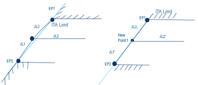
- In the case below, an extra junction line is created.
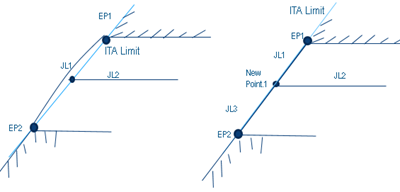
- In this last case, the junction line deviated from the ITA limit, because of the
high curvature of the underlying surface. After optimization, it is correctly
aligned.
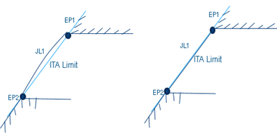
- In the case below, the number of junction lines remains the same.
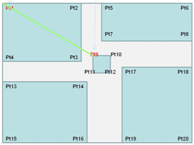
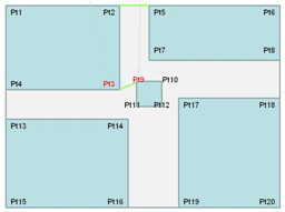
- A set of Imposed Thickness Points (ITP Set) is created. The ITPs are identified in the 3D area. Solid From Iso-Thickness Areas uses this ITP Set to ensure that the elevation height/offset at these points is equal to the thickness specified with the ITP.
Tip: Verify the optimization result under Check and Refine Results. - Small inaccuracies found in the selected junction lines are corrected during
computation. Below are three examples of correction when there is a gap between the
junction line and the ITA limit:
-
Click Compute.
- The wizard finds all the points at the corners of the iso-thickness areas of the group.
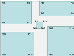
- If a line between two points intersects an iso-thickness area, this line is not considered a potential junction line.
- If a line between two points does not intersect an iso-thickness area, this line is considered a potential junction line.
- The analysis produces several groups of points.

- If a group contains only two points, the line between those two points is proposed as a junction line.
- If a group contains more than two points, they are joined two by two. If plies corners coincide with a line, this line is proposed as a junction line,
otherwise it is not.
The dialog box is populated with the result of the computation. The groups are displayed in the order of the statuses:
- Red traffic light: No junction line found or proposed.
- Yellow traffic light: A junction line has been found or proposed, but your validation is requested.
- Green traffic light: A junction line has been found or proposed, and seems to be correct.
- Validated (green marker): A junction line has been found or proposed, and you have validated it.
The groups of points are also displayed in the work area:
- With their thickness.
- With the traffic light representing their status.
- With a dotted green line is the status is green but not yet validated.
- With a solid green line when it is validated.
- With a solid blue line when the junction line is part of an existing set.


- The wizard finds all the points at the corners of the iso-thickness areas of the group.
-
In the 3D area, drag the cursor over a vertex.
The two ramp supports that intersect at this vertex are displayed.

-
Click a point
and drag the cursor.
- The dotted line is red, until you pass the cursor over another point.
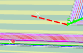
- If that point belongs to another iso-thickness area, or is a standard point, the dotted line
turns green, meaning a junction line is created between those two points.

- If that point belongs to the same iso-thickness area, this iso-thickness area is relimited by
the dotted line. Note: The iso-thickness area can be relimited or trimmed.
- The dotted line is red, until you pass the cursor over another point.
- To remove any potential or validated junction line, drag the cursor over the line until a red cross appears. Click that red cross.
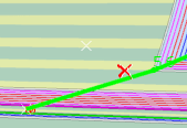
The junction line is removed from the preview and not created.
Junctions lines are created either in the geometrical set containing existing junction lines you have selected, or in a new geometrical set named Junction lines (Generated by wizard):
- Junction lines previewed as solid green lines, that is, validated by you, are created.
- Junction lines previewed as dotted green lines, that is, not validated by you, are not created. A message is displayed.
- Junction lines previewed as blue lines, that is, existing and not modified, remain unchanged.
- Junction lines that you have removed from the preview are removed.
Iso-thickness areas are relimited, if need be. The geometry required to perform this relimitation is added below the iso-thickness area node in the tree.