Creating Splice Plies from Producibility | |||
| |||
-
From the Producibility and Splicing section of the action bar, click Splice Plies from Producibility
 .
.
-
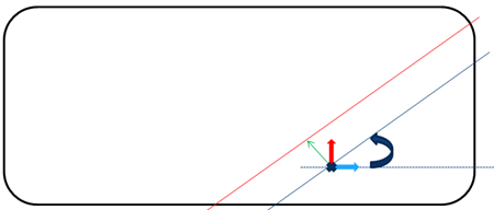
Enter the Fiber Mesh Parameters.
- Point: Start point (cross). Fiber mesh curves are created on the plane tangent to the ply reference surface at the start point.
- Distance: Offset value applied to the rotated curve to build the result curve (green arrow).
- Angle between the Warp vector and the result curve (circular arrow).
-
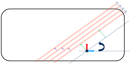
Enter the Splice Parameters to create the parallel curves (in red below).
- Staggering: Distance between the curve on a given ply and the curve on the next ply (purple arrows).
- Overlap between to consecutive cut-pieces.
- Repeat: Defines on how many plies the staggering is applied from the start position (in the example below, 4).
- Offset: Distance by which the start position is translated to avoid cut superposition.
-
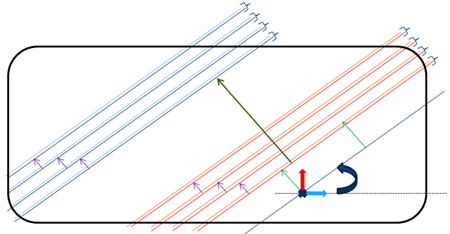
Select Repeat using Material Roll Width to create all the cut-pieces in one shot.
Below, the roll width is shown by the dark green arrow.
A 3D Multisplice Group is created. It contains a MultiSplice From Producibility node with:
- Provided parameter values (staggering, overlap, repeat status and associated offset).
- A Group of FiberMeshCurves.
Note:
The generated cut-pieces do not support No Splice Zones nor Butt Splice Zones: The result could be larger than the roll width. In the example below, the No Splice Zone is the red square.
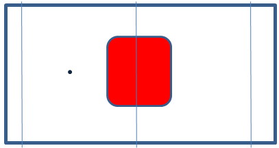
With the current start point, the cut-piece shown in orange is larger than the roll width.
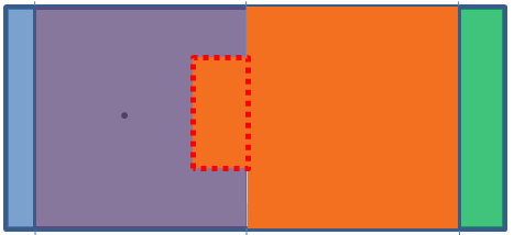
By-pass: Move the input point to create curves outside the No Splice Zone.
With the current start point, the cut-piece shown in orange is larger than the roll width.
By-pass: Move the input point to create curves outside the No Splice Zone.