-
From the Review section of the action bar, click Numerical Analysis
 .
.
The Persistent and the Take cut-pieces into account check boxes are not active when you have selected zones.
-
Select the element to analyze:
- A grid
- A stacking or portion of it
- A zones group or portion of it.
- Multiselection of entities
 is available.
 in the
dialog box that appears gives access to the Stacking Management.
in the
dialog box that appears gives access to the Stacking Management.
The analysis is automatically started, displaying the
results under Analysis.
-
If required and possible, select the Take cut-pieces into
Account check box.
The analysis is updated with the information concerning the
cut-pieces.
Notes:
- The values increase as the result of the plies superposition.
- To compute the Area, and the weight and balance,
Numerical Analysis considers that all plies lie directly on
the support surface. This means that the area of an individual ply is computed by trimming the support surface by that ply contour. This
assumption impacts all related properties (such as the center of gravity). Also the
thicker the stacking, the less accurate the result is.
The numerical analysis of all the plies can now be exported in an external file
(.xls or .txt).
-
If required, select the Take Core thickness into Account check
box.
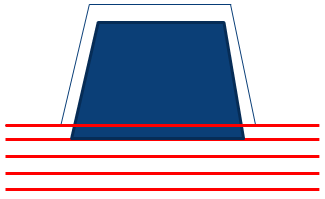
- When Take Core thickness into Account is not selected, the
computed area for plies looks like this
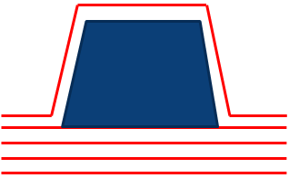
- When Take Core thickness into Account is selected, the
computed area for plies looks like this
The analysis is updated with the information concerning the
Core Thickness.
-
If required, select the Compute analysis with ply and core shape simulated
at thickness check box.
- Compute analysis with ply and core shape simulated at
thickness is more time consuming but also more precise.
- Compute analysis with ply and core shape simulated at
thickness includes Take Core thickness into
Account
- Optional:
Edit the Refinement Factor.
Refinement Factor improves the accuracy of the tessellation
used to compute the numerical analysis, but has an impact on computation time. The
lower the value, the greater the accuracy of results, but also the computation time.
The minimum value is 0.02. The maximum is 10. The default is 1.
- Optional:
Select the Display normals check box.
The normals used for elevating each vertex of the tessellation triangles are
displayed. The normals direction and their density help you specify the
Refinement Factor.
-
Press Compute.
Messages are displayed if there are errors on plies, or if a core does not lie
completely on the support surface.
Notes:
- Results of this option are not persistent: you have to export them to keep them.
- If plies are defined on two overlapping support surfaces, the thickness of plies
on first surface is not considered for plies lying on the second surface.
Recommendation:
In such a case, define all the plies on a larger single
surface.
- If the top surface computed from Plies Group.1 is used to define plies from Plies
Group.2, the thickness of plies added to Plies Group.1 after the computation of the
top surface is not taken into consideration for the computation of plies from Plies
Group.2.
Recommendation:
In such a case, recompute the top surface after
having added plies to Plies Group.1, and define the plies from Plies Group.2 on
the new surface.
-
Click ... to enter a storage directory and file name to export the data. Click Export.
An information message is displayed when data is successfully
exported.
Here is the information contained in the external file:
- For zones:
- Zone name
- Thickness (mm)
- Number of layers
- Area (m2)
- Volume (m3)
- Volumic Mass (Kg)
- Aerial Mass (Kg)
- Centre of Gravity-X (mm), Centre of Gravity-Y (mm),Centre of Gravity-Z (mm)
- Cost.
- For plies:
- Ply Group
- Sequence
- Ply/Insert
- Material
- Direction
- Area (m2)
- Volume (m3)
- Volumic Mass (Kg)
- Aerial Mass (Kg)
- Centre of Gravity-X (mm), Centre of Gravity-Y (mm),Centre of Gravity-Z (mm)
- Cost.
-
Select a Material to filter the results.
Filtering through Material is only possible if you have
selected at least a stacking as input.
-
If available, select the Persistent option to featurize and
display the analysis in the tree.
The
numerical analysis is stored under the representation if you have selected
plies.
The Numerical Analysis element is displayed in the stacking node
under each sequence containing the selected material.