Creating Plies Sections | ||
| ||
- From the Review section of the action bar, click Plies Section
 .
.
- Select the Section type.
- Select a Display type.
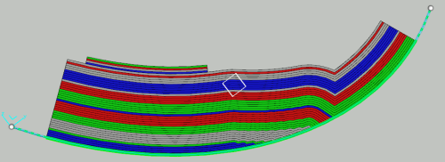
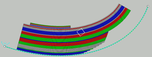
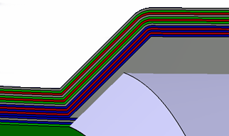
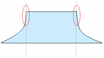
- Optional: Key in a Scale factor by which the thickness of the element (ply or insert) is multiplied
in the section view as shown by the arrow in the picture below:
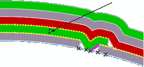
The Scale factor introduces a deformation of the section as shown below:
- At the top, the Scale factor is equal to 1.
- At the bottom, it is higher than 1.

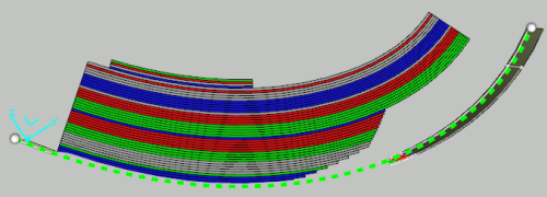
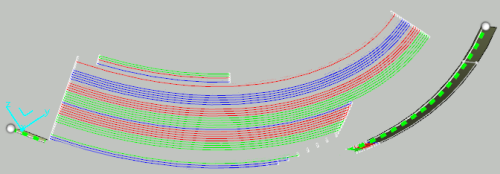
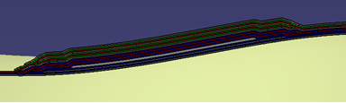
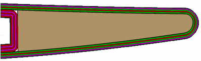
- Optional: Select the Apply scale on cores check box for a better understanding of the plies when cores exist.
- The scale factor (10) is not applied to the cores.
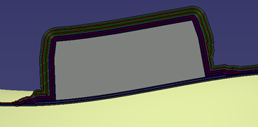
- The scale factor is applied to the cores.
- The scale factor (10) is not applied to the cores.
- Optional: Decide to keep the position of cores, or not.
By default, Keep core position is not selected. In a case like this one
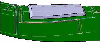
this means that the section shape of the core is repositioned between the plies at the right position as shown below:- View of the 3D section and core as defined in 3D area:
- View of the section only:

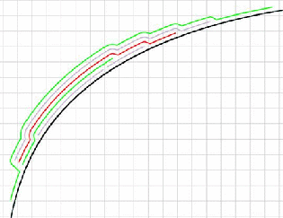
However, in some cases, for example on highly curved reference surfaces, or core shapes, the repositioning of the core in the 3D section is impossible.
In such cases, when the core is designed at its correct position, for example on the top surface of the plies below the core, repositioning is not required. Selecting Keep core position provides a correct result. - View of the 3D section and core as defined in 3D area:
- Click OK.
- The sections are created in the work area.
- If it did not already exist, a Review tools is created in the tree.
- A 3D Sections node is created under Review tools.
- Each time you create a set of sections, it is added to the 3D Sections node, as 3D Section.x
- This set contains the created sections, named Section of Ply.x or Section of Cut-piece.x.
Notes:- The following two types of cores are not supported:
- Cores with concave sides:
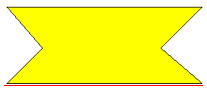
- Cores with this shape

are deformed into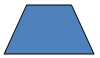
- Cores with concave sides:
- Ramps tangent to the normal of the reference curve can lead to
instabilities:
or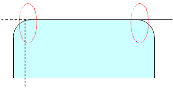
- Ply Sections in Drawings: If a Drawing view points to a ply section and corresponds to the same
plane as the ply section, the ply section is visible in the Drawing
as illustrated below.
- Surfacic or block linear ply section:

- Light linear ply section:
- Surfacic or block linear ply section: