Creating a Solid or a Top Surface From Zones

You can create a solid or a top surface from the zones you defined for the Composites part.

Notes:
  • This task is available in Composites Design.
  • You can use Zones Groups created with the For Solid From Zones Creation Only check box.

This task shows you how to:

Create a Solid

You can create a solid.

  1. From the Zones Design section of the action bar, click Solid From Zones .
  2. Select the group of zones you want to solidify.

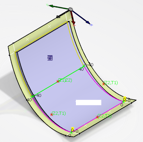
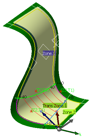
  • The Solid is created in the tree, under a PartBody.

  • The solid thickness corresponds to the addition of all thicknesses of all materials (as defined in the Material catalog) used to design the Composites part.
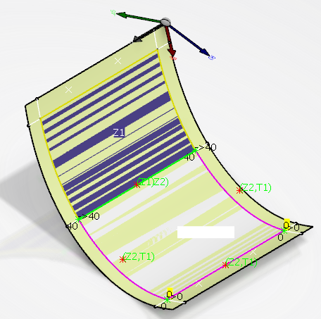
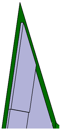
  • If you select Solid without Transition-Zones, only zones are solidified and a rough solid is generated. With such a solid, you can visualize the space allocation of the part.

Create a Top Surface

You can create a top surface.

  1. From the Zones Design section of the action bar, click Solid From Zones .
  2. Select Top Surface.

A Top Surface From Zones is created in the tree, under the Top surface node.

Create a Top Surface with Shape Morphing

You can create top surfaces using a shape morphing.

  1. From the Zones Design section of the action bar, click Solid From Zones .
  2. Select Top Surface and Use Shape Morphing.


The generated top surface with shape morphing is based on the transition zone refinement curves and takes into account the curvature of the surface:

  • Section view of the top surface generated with shape morphing:

  • Section view of the top surface generated without shape morphing:

Create a Solid with a Zero Thickness

You can create a solid with a zero thickness: when you design a model with reinforcement areas based on zones and transition zones, the solid requires an edge going down to the level of the reference surface of the zone to minimize the thickness.

  1. Double-click the zone to verify that the laminate is empty.
  2. From the Zones Design section of the action bar, click Transition Zone and select the zone above as Zone/Zone Group.

    Select the contour of the zone so that the transition zone fully covers the zone.

  3. From the Zones Design section, click Connection Generator 
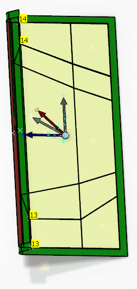
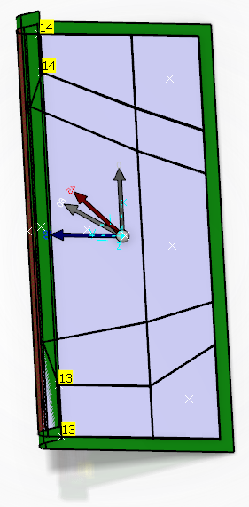
to display the thickness points.
  4. Select the zone group to be analyzed and click Apply
    In our example, the thickness points are not computed between the zone and its transition zone.

  5. Click ITP .
  6. Select a vertex.

  7. Create another ITP.

  8. Rerun Connection Generator on the Zones Group.
    This time, all the thickness points are displayed including those having a zero thickness.

  9. From the Zones Design section, click Solid From Zones .

The solid is created with its edge going down to the level of the zone.