Swapping the Skin with Wrap Curve | ||
| ||
- From the Skin Swapping and Ply Extensions section of the action bar, click Skin Swapping
 .
. - In Stacking (Manufacturing), select the feature where you want to insert the swapping.
- Multiselection of entities
 is available.
  in the dialog box gives access to the Stacking Management.
- It can be a ply, a sequence, a group of plies, cut-pieces, an edge of part or a stacking.
- As Edge Of Part and Swapping are not symmetric operations, the skin swapping of an EOP created from plies is not strictly equal to the EOP created from swapped plies.
The engineering surface to be swapped is already selected under Swap.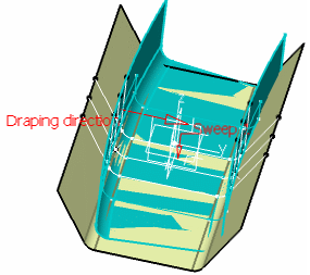
- Multiselection of entities
- Select the manufacturing surface to be swapped with.
 Its name is displayed in the dialog box under With.
 -
Select the Curves
tab, click
... and select the first reference curve
then the first target curve.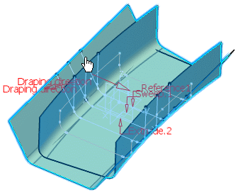
- Select as many reference/target curves pairs as required.
- You can insert or remove pairs as required.
Important: - Select the reference curves and target curves as pairs: Do not select all the reference curves, then all the target curves.
- When selecting several pairs of curves, select them in order, not randomly.
- Reference curves should not intersect each other, nor should the target curves intersect each other.
-
Optional: Define further constraints on the deformed ply shell.
You can choose to retain the initial ply shell curvature or tangency constraint on the first pair of curves, on the last pair of curves, or on both pairs of curves.
If you select Keep tangency or Keep curvature, the original continuity between the deformed area and the surface outside the deformation area is kept as best as possible, but may be approximate in certain cases.
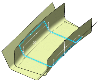
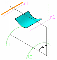
For each ply, the ply shell is computed, then the ply shell is deformed. The following diagrams help you understand how the deformation is computed in relation to the entered data, that is, reference/target curves and possible spine.3D view, where:
- r1, r2 are the reference curves,
- t1, t2 are the target curves,
- P is a plane normal to the spine (orange line).
Planar view, where:
- Ir1: is the intersection between P and r1,
- r2: is the intersection between P and r2,
- It1: is the intersection between P and t1,
- It2: is the intersection between P and t2.
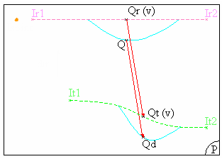
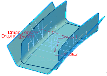
The deformation is computed in each plane P, normal to the spine.In each plane P, the system computes the intersection between the plane and each curve.
A curve (Cr) is created between the first intersection point (Ir1) and the last intersection point (Irn) on reference curves, passing through all the intersection points between these two.
Similarly, a curve (Ct) is created passing through all the intersections points between the first (It1) and the last intersection point (Itn) on target curves.
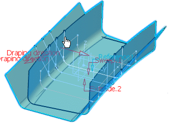
Then, for each point Q, resulting from the intersection of the surface to be deformed with the plane, Q is projected onto the curve Cr according to the projection direction (dir).
This projection direction is the vectorial product of: Vector(lspine, lr2) ^ vector normal to P.
The result of the projection of point Q is the point Qr, its parameter on Cr is v.
Similarly, a point Qt is created on the curve Ct, with the same v parameter as point Qr on curve Cr.
Then Qd, that is the transformation of point Q according to the wrap curve deformation, is obtained by adding: Q+vector(Qr,Qt).
The boundary of the deformed ply shell is computed and is specified as the result contour of the skin swapping.
In the tree, the Swapping feature (identified as Swapping.xxx) is created under the ply and a Skin Swapping Group is created under the Stacking.