Maximizing the Symmetry | ||
| ||
-
Set Entity level to Sequence.
The initial Virtual Stacking is as follows:
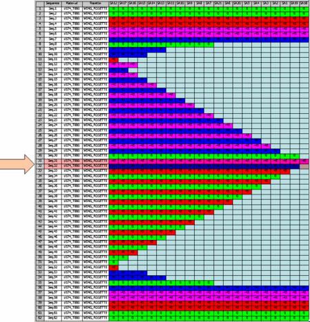
with only one material and the following orientation color code:- red: 45
- magenta: -45
- blue: 90
- green: 0
-
Select Maximize Symmetry
 from the Tools Palette.
The Maximize Symmetry dialog box appears with the ordered list of orientations to use, for example
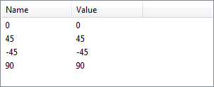
and the number of sequences to process.Notes:- At the first start, this list is the same as the one defined by Composites Parameters in the Directions tab. It is saved in your local options for future use.
- When you start Maximize Symmetry again, the orientations
saved in your local options are compared to the current ones of
Composites Parameters (number, values):
- If a difference is found (different numbers, orientation not found in Composites Parameters), the orientations of Composites Parameters are used (reverting to reinitializing the list of Maximize Symmetry).
- If the contents in the same, with only a different order, the orientations of Maximize Symmetry are used.
- Click OK in the Maximize Symmetry dialog box.
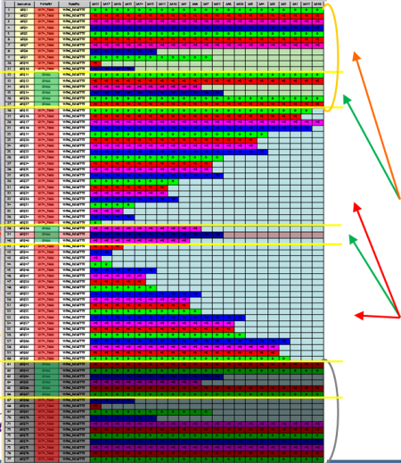
- The sequences shown by the arrows have been added to exact symmetry zones (we have temporarily
locked the symmetry on the result to highlight the exact symmetry zones with yellow
and gray filters).
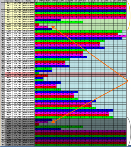
- The orientations alternate according to the order you have defined, for example
- green: 0
- red: 45
- magenta: -45
- blue: 90
- green: 0
- red: 45
- blue: 90
- magenta: -45
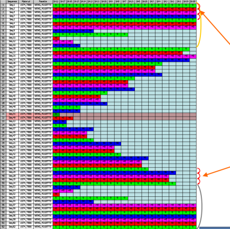
- Regarding the cell coverage criteria, layers are ordered by cell coverage, from layers covering the greatest number on outer boundaries of the Virtual Stacking (top and bottom) to layers covering the smallest number of cells at the center of the Virtual Stacking.
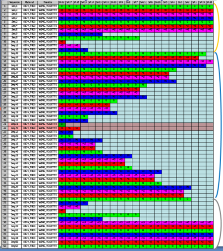
- The symmetry of layers is maximized on thicker cells or stacking areas.
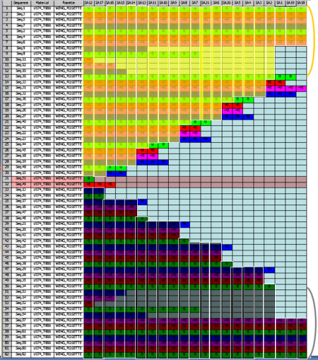
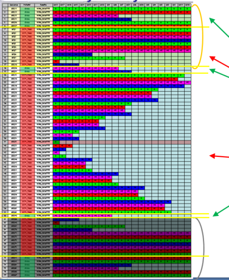
- The sequences shown by the arrows have been added to exact symmetry zones (we have temporarily
locked the symmetry on the result to highlight the exact symmetry zones with yellow
and gray filters).
-
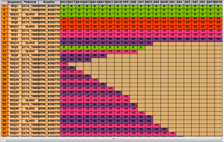
Let us consider the same Virtual Stacking, but with several materials, for example:
- U174_T800 in orange below
- GLASS in green below
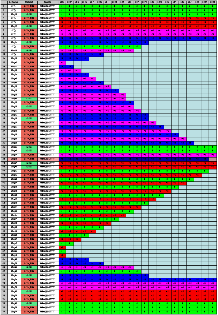
- Click OK in the Maximize Symmetry dialog box.Maximize Symmetry uses the same material order as the one defined by Composites Parameters, here:
- U174_T800 (shown in orange below)
- GLASS (shown in green).
You can change that order in Composites Parameters.
Maximize Symmetry orders:- Layers of the first material, then of the second material in the exact symmetry zone, (we have
temporarily locked the symmetry on the result to highlight the exact symmetry zones
with yellow and gray filters),
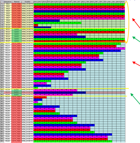
- Then does the same in the non-symmetric zone.
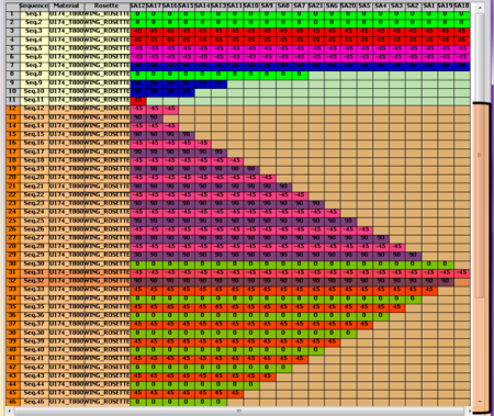
If you invert the order of materials in Composites Parameters:- GLASS (shown in green)
- U174_T800 (shown in orange below).
-
You can filter the selection of sequences to process.
All sequences to process are selected.
-
Press Ctrl key and select one row in the Virtual Stacking, or press Shift to select
several rows.
They are removed from the selection to process.
- The information is updated in the dialog box.
- The selected rows are not moved when you click OK.
-
Select Lock Symmetry.
Only the virtual sequences belonging to the neutral zone are selected to be processed.
- You cannot select row in the real symmetry top and bottom zones.
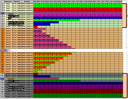
- You can filter virtual sequences only in the neutral zone.
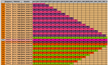
resulting in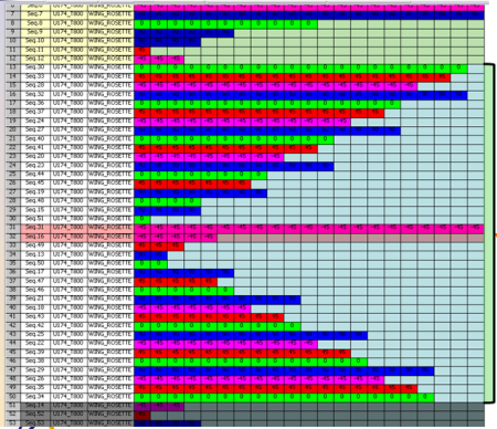
The new found real symmetrical virtual sequences are automatically included in the top and bottom real symmetry zones.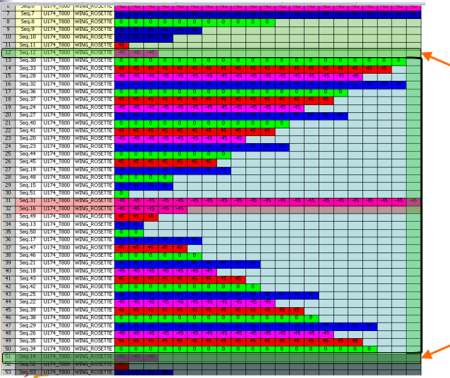
- Only selected rows are moved when you click OK.
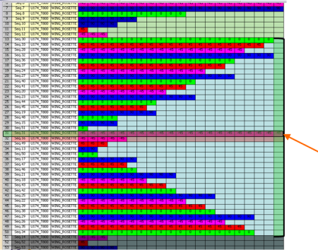
- The information is updated in the dialog box.
- You cannot select row in the real symmetry top and bottom zones.
-
Press Ctrl key and select one row in the Virtual Stacking, or press Shift to select
several rows.