From the Develop section in the Generative Shape Developapp, click Unfold.
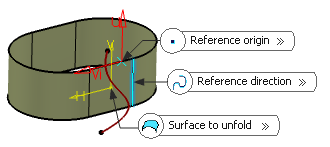
In the Surface to unfold box, select the surface to be unfolded.
Note:
If the surface to unfold has no vertex belonging to one face
(for example, a closed surface), the reference origin and
direction are not automatically valuated. On the contrary, they are valuated if a vertex on the edge
of the surface is found. The result is positioned such as
this origin and its image as well as the tangent to this
direction and its image are coincident.
The surface must be connected and manifold. When the local axis
system is modified, all related features are updated.
In the Origin box, select the reference origin that is a point on the surface to unfold.
If no specific origin is selected, it is set to Default. By default, when possible, a corner of the surface to unfold is selected. If a target plane is defined and a projection is possible, the origin is defined as the projection of the point, selected as the origin on the surface to unfold, onto the target plane. If not, the origin of the axis system of the target plane is selected as the default origin.
In the Direction box, select the reference direction that is the edge of the surface whose extremity is the point.
Note:
The reference direction is determined by the projection of
the reference direction onto the plane tangent to the surface to unfold
(Ui).
If no specific direction is selected, it is set to
Default. By default, when possible, an edge
of the surface to unfold is selected. If a target plane is defined and a
projection is possible, the direction is defined as the projection of
the tangent to the selected edge onto the target plane. If not, the
direction of the target plane is selected as the first direction of the
axis system of the target plane.
If the reference Origin lies on an edge to tear,
the Reverse direction is enabled and a blue arrow
is displayed in the work area.
Click the blue arrow in the work area or the Reverse direction in the
Unfold Definition dialog box to reverse the
orientation of the resulting surface.
Optional:
In the Plane box, select the target plane on which the surface has to be unfolded (here we chose yz plane).
The plane is defined depending on the origin and the direction of the surface to unfold.
Optional:
In the Origin box, select the target origin.
Optional:
In the Direction box, select the target direction.
Important:
The target direction is determined by the plane tangent to the surface to unfold (Vi).
Select the Reverse Uf check box to reverse the final U direction.
Select Reverse Vf check box to
reverse the final V direction and Swap check box to
reverse both Uf and Vf directions.
If Swap as well
as Reverse Uf and Reverse
Vf check boxes are selected, the swap is performed
before the inversions.
Click Preview.
Flag notes display candidate curves to tear (if any) in the work area.
The unfolded surface is positioned on the selected plane such
as:
The image of the selected point on the surface to unfold coincides
with the selected point on the plane.
The image of the tangent to the selected edge on the surface to
unfold is collinear with the selected direction on the plane.
Tip:
If you move the pointer over a flag note, a longer
message giving an accurate diagnosis is displayed.
The
Curves to Teartab lets you select as many internal and external curves or edges to tear
as required. Along the selected elements, a surface is developed, so
that constraints are solved.
Select the curves to tear.
Click either the 3D flag or the curve or the edge.
If no edge of the surface can be defined as candidate, an
information message is issued and the Curves to Teartab displays a list of edges to be selected. The selection of curves or edges
to tear is optional if there is no curve or edge to tear.
Tip:
To cancel the selection of a curve to tear, click
it. The selection is possible again.
Unfold using an internal edge to tear Unfold using an external edge to tear
Click OK to unfold the surface.
Unfold using an internal edge to tear Unfold using an external edge to tear
Select the Surface Type
You can select the surface type of the unfolded surface.
Click Unfold.
The Unfold Definition dialog box appears.
In the Surface to unfold box, select the surface to be unfolded.
Click More>>.
Select one of the options for Surface Type:
Ruled (by default): allows you to unfold a ruled surface only. If the surface is not ruled, an error message is issued. It computes an exact unfold of the input surface. The area and lengths of the surface are kept in the final result.
All (in our scenario): allows you to unfold
any surface. If the surface is ruled, a warning message is issued
offering you to switch to the Ruled type. It
computes an approximation of the flattened surface. The area and
lengths of the input surface may differ from the area and lengths of
the unfolded elements.
Note:
The symmetry of the unfolded surface
(created with All surface type) may not
be kept in the flattened result.
Select the Display optional edges to tear check box to display the candidate curves or edges to tear in the work area.
Important:
This option is cleared by default as well as while editing (even
if selected previously).
This option is available with All surface type.
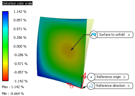
In the Distortion color maps area, you can:
Select the Unfolded surface check box to display distortions of the unfolded surface.
Select the Permanent check box to display the distortion of the unfolded surface permanently.
Note:
This check box is available with the Unfolded surface check box only.
Select the Surface to unfold check box to display distortions of the input surface. This helps to map the distortions of the unfolded surface on the surface to be unfolded.
Important:
The distortion options are only available with All surface type. They are unavailable otherwise.
The Distortion color scale displays the maximum and minimum percentages of length distortion. A positive distortion means that the flattened surface is stretched, while a negative distortion means it is shrunk.
Important:
Click Shading with Material from the View section of the action bar to visualize the distortions correctly. If another mode is selected, a warning message is displayed.
Click OK.
The developed surface (identified as Unfold.xxx) is added to the tree.
Notes:
The distortion color scale is no longer visible in the work area after completion of the command.
Performing a local Undo is unavailable with this command.
You can also display the distortion after the surface is unfolded. Right-click Unfold.xxx and select Display distortions or Remove distortions to display or remove the distortions.
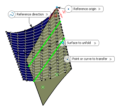
Define Curves or Points to Transfer
You can define curves or points on the surface to unfold.
Click Unfold.
The Unfold Definition dialog box appears.
In the Surface to unfold box, select the surface to be unfolded and click Preview.
In the Transfertab, select the points or the curves on the surface to unfold or on the unfolded surface.
Select the type of transformation:
Unfold: transfer the elements on the unfolded surface.
Fold: transfer the elements on the surface to be unfolded.
Note:
Click Remove or Replace to remove the selected element or replace it by another element.
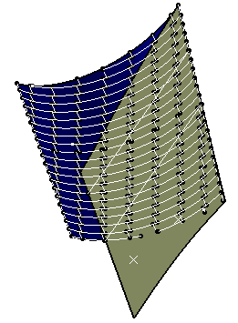
Click Preview to see the unfolded surface and elements.
Click OK to unfold the surface.
The developed surface (identified as Unfold.xxx) is added to the tree, as well as the transferred elements.
Tips:
Mono- and multi-cell surfaces, as well as closed surfaces can be unfolded.
Multi-cell surfaces and surfaces with internal loops can be unfolded.
If no point or direction that is not linked to the edges to tear can be selected on the surface to unfold, you can split the surface to unfold (using Keep both sides to retain the Split element after the operation) and unfold both sides.
 .
.