Power & Free Conveyor Concept | ||
| ||
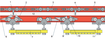
The key elements of a P&F system are:
- Driver Cam - track section that contains the power chain.
- Retaining Catch - holds the trolley on the pusher dog
- Power Chain - - a chain that is moving continuously at a constant speed. Power chain is not modeled directly in our software. It is defined through dog/pusher definition, which itself is defined as a part of section definition.
- Pusher Dog - a metal rod that is attached to the power chain and whose role is to push the trolley. Dogs are always of the same shape/size and are always at a constant distance from each other. It is not modeled but dog spacing will be defined as part of section definition.
- Power Track - the track that has power and moves the trolley.
- Free track - the path that a trolley will be following while moving: this is selected by you during the section creation.
- Carrier / Load bar - the part of the trolley. This is a simple, mechanical device that is pushed by the dog (aka. pusher) and that moves along the track on a set of wheels. Connection between a trolley's lever (8,9) and a dog is in the form of a simple contact. Contact is maintained for as long as the level is in the upright position (1). If a level tilts due to contact with another trolley or another piece of equipment, (8.9) contact is lost and the trolley stops moving. Furthermore, a trolley remains stationary until the blocking condition is removed, which tilts the lever in the upright position. As soon as the next dog comes in contact with the level, the trolley starts moving.
- Contact Skid - the part that released the following carrier from the pusher dog.
- Contact Cam - part that makes contact with the trolley in front that releases the pusher dog.
- Front Trolley - Front of the trolley
- Rear Trolley - Rear of the trolley
- Dog Spacing - represents the distance between two consecutive dogs.
There are different types of points for different types of usage.
- Trolleys are mounted in the free lane for clarity
- Reference points are defined in the conveyor but they are using geometry defined on the trolley. A trolley is pushed along the line by a dog. To prevent crashes between two trolleys a disengagement mechanism was developed. Thus, if a trolley gets in contact with a trolley in front of itself, it disengages from the power chain. A reference point is used to figure out when to disengage from the power chain. By simply measuring the distance between two consecutive reference points, the Safety distance can be determined when such disengagement should take place.
- Reference points are used to indicate when the Decision Zone is triggered as well as when the trolley crosses sections.
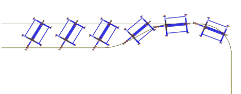
Section - represents a rail on which a trolley freely moves. A section can be of a different shape such as linear, circular or concave/convex.
Biasing - in general the P&F conveyor sections are formed of a single free track that the trolleys move on; however, a special setup called biasing, where the track is formed of two tracks, and thus the trolleys will split between them: they are useful for accumulation zones or banks, to save space and an effective strategy is to maintain a float (generally set to one-half hour to one hour of production) on the chains. The float has to be spread out along the length of the loaded section of the power and free system. Bias accumulation banks provide a means for storing float with minimum space requirements.
