Create a New Template from an Existing Mechanism
You can save the kinematics from an existing mechanism as a template that can later be used to easily define the joints of predefined kinematic chains.
-
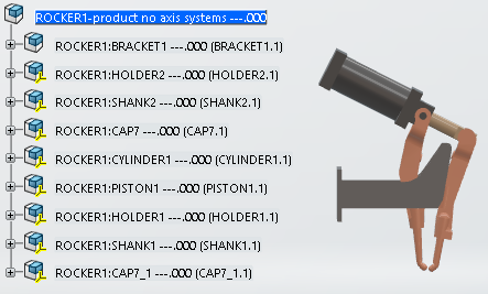
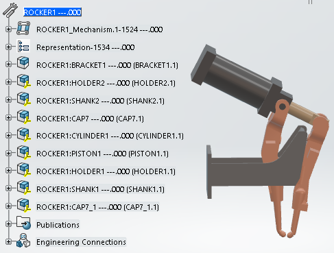
Open an existing mechanism that has kinematics defined.
-
From the Kinematics section of the action bar,
click Kinematics Wizard
 .
.
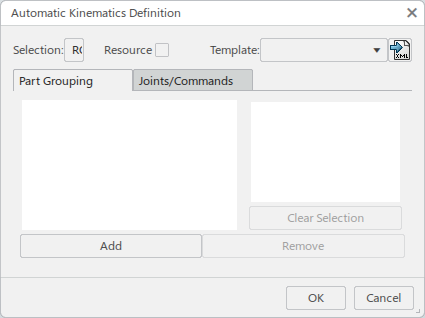
The Automatic Kinematics Definition dialog box appears.
- Selection displays the name of the current selected object.
- Resource converts the selected product into a tool equipment resource with a controller. If the selection is already a resource, Resource is automatically selected and disabled. If certain options (such as kinematic relations) require a resource type, Resource is automatically selected and disabled.
- Template is automatically set to Custom.
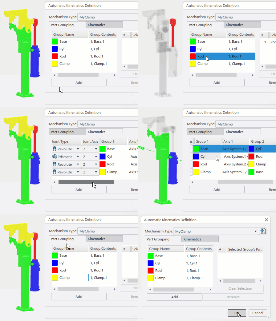
- The Part Grouping tab and the Joint Types in the Joints/Commands tab are populated from the existing kinematics.
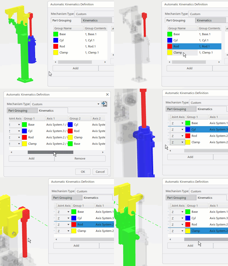
Note: The default color for each group name can be customized by clicking the color swatch next to the group name.
-
In the Part Grouping tab, select a group in the
Group Name column.
The parts that are included in the selected group appear in the Selected Group's Parts list.
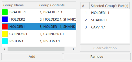
Click Add to select a part in the work area or tree to add it to the current group.
Click Clear Selection to remove a selected part from the current group.
Click Remove to remove the entire group.
-
Click the Joints/Commands tab to view and edit the current
defined kinematic relationships and axis definitions.
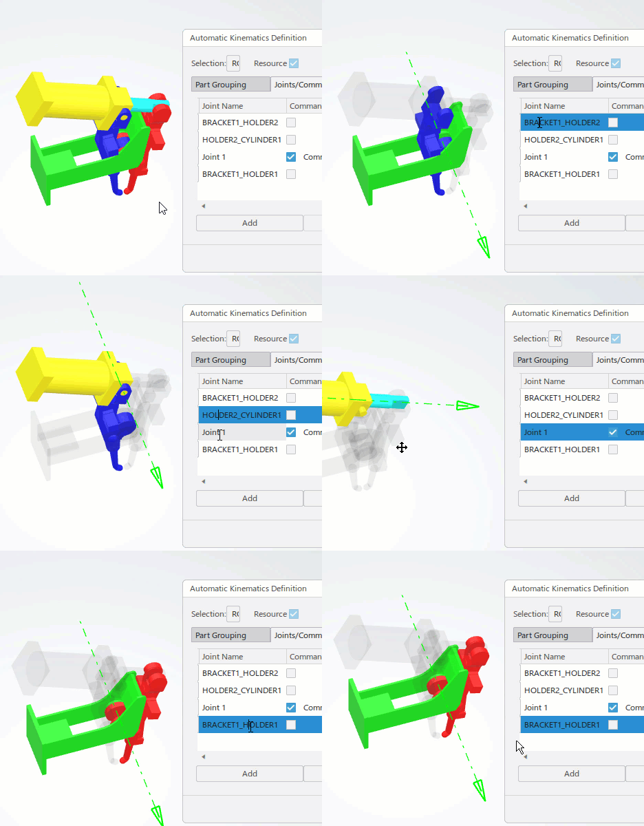
For each defined joint:
- You can select the type of joint from the Joint Type list.
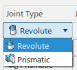
- Joint Axis specifies the axis for the joint.

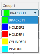
- Group 1 and Group 2 specify the
respective group from the list of defined groups.
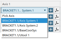
- Axis 1 and Axis 2 allows you to
select from the defined axis systems of parts directly added to the current group.
Click
 to define a
new axis system for the current group.
Click
 to edit the
axis system that is currently selected.
- Joint Name displays the name of each joint. A joint name is
required when defining joint relations. You can edit the name directly in the
respective field.

- The Command column lists the defined commands and their
respective names. Selecting a joint as a command requires a name for the command.
Clearing the selection deletes the command and clears the name.

- You can select the type of joint from the Joint Type list.
-
Click the Relations tab.

This tab facilitates the management of joint relations. It lists all non-command joints and displays any relations that are defined on them.
Click Add/Edit to launch the Define Joint Kinematic Relations dialog box and manage a relation for a selected joint.

Click Remove to remove a selected relation.
-
When the kinematics are defined as needed, click Save Template
 to save
the current kinematics settings as a template that can be applied to other
products.
The Save Template dialog box appears, and prompts you to name the template.

Templates location is set by default to the KinematicsTemplates folder under your user Documents folder. The default location can be customized in Me > Preferences > Simulation > Digital Manufacturing Apps Common Services > Device Analysis > Kinematics Wizard > Templates location.

-
Click Save to save the template.
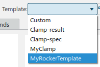
When you subsequently open data that has no kinematics defined, the saved template appears for future use in the Template list.
