Managing Mechanical Ports

A mechanical port specifies a position of the mechanical assembly to be used when attaching and mounting connections with other resources. By default, this position is the center of the part. You can select a different position by using a predefined axis system.

A robot resource typically has:

  • a base port, where another resource can attach the robot
  • a mount port, where any tooling can be mounted

A tool device resource typically has:

  • a base port, where the tool can be attached by another resource
  • a tool port, where the tooling area of interest is

  1. From the Resource Creation section of the action bar, click Mechanical Port .

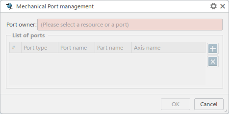
    The Mechanical Port Management dialog box appears.

  2. Select a resource in the work area.

    List of ports lists all existing ports defined on the selected resource.

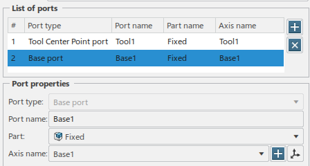
  3. Select a port in the List of ports.

    The Port properties section appears, and provides details about the selected port.

    • Port type indicates one of the following types:
      • Base indicates the location on the resource that is snapped to a mounting location (defined through a mount port).
      • Mount indicates the location where the current resource mounts a tool (that has a base port).
      • Tool Center Point (TCP) indicates the working location tip of the resource.
      • Connector is used to lay out two different resources between them (with each resource having a connector port).
      • Locator is used to define a unique origin location per resource.
      • Tool mount is the mounting location for the tool.
      • Workpiece mount is the location where a workpiece is put.
      • Head base indicates the location on the Head that is snapped to a mounting location (defined through a mount head).
      • Mount head is the mounting location of a resource for a head tool.
      Note that the Port type cannot be changed once the port has been created.
    • Port name must be a unique name within a given context owner. It cannot be empty.
    • Part is the part owning the axis system. It lists all parts under the selected resource.

    • Axis name is the part’s axis system. It lists all axis systems under the selected part.

      A port is related to an axis system and is used to indicate its location. If the axis location changes or is replaced, the port remains and represents the location to be used outside of the current resource.

      An axis has a port icon if it is already used by another port. If an axis has no icon, it can be used by the current port.

      A new axis system can be created with . The position of an existing axis system can be modified with using the standard snapping point context toolbar. If the selected part does not have any axis systems, a warning icon appears and you are prompted to create one.
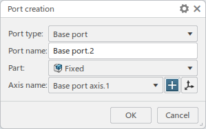
  4. From the List of ports section, click to create a new port.

    The Port creation dialog box appears.

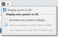
    Click to control display preferences.

    • Display ports in 3D allows you to visualize a color coded and labeled axis system for each port.
    • Activate axis systems display allows you to visualize the axis systems in 3D, either All axis systems under the context or those Axis systems under the current part.
  5. From the list, select a Port type

    .
  6. From the Axis name section, click to define the location for the new port.

  7. Click OK to confirm the selected location and create the new port.

    The mechanical port is created at the selected location and appears in the List of ports.

Note:

Mechanical ports are part of the specification of the device, therefore the port definition is part of the device reference. This means that:

  • When defining a new port on a device instance, the port is created on the device reference and all device instances reflect the new port.

  • Removing a port on a device affects any previously defined attachments.