Building a Mechanism | |||
| |||
-
From the Kinematics section of the action bar, select Define Kinematics
 .
You are prompted to select the child part for the joint.
.
You are prompted to select the child part for the joint. -
Select a part in the work area.
The context toolbar is displayed.
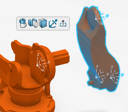
The context toolbar allows you to select the type of joint to create.

Revolute Joint 
Prismatic Joint 
Rigid Joint 
Fixed Joint -
Select a joint type in the context toolbar.
If you select Fixed Joint
, the selected part is marked as the fixed part and a corresponding engineering connection is created under Engineering Connections in the tree.Note: There can be only one fixed part for a mechanism. If another part is subsequently selected and defined as Fixed Joint, only the last selected part will be considered the fixed part.If you select Revolute Joint
, Prismatic Joint or Rigid Joint, the orientation Robot snaps to the axis of the selected part and a context toolbar provides options for defining the plane.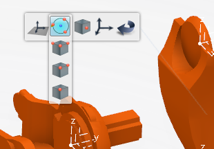
Joints are created as engineering connections that are based on the axis systems defined for the selected parts. By default, the joint is created at the origin of the child part, and is selected automatically when you select the joint type. The tools provided in the context toolbar allow you to specify an exact point where a new axis system can be created and used to create the joint.
-
To define an axis other than the default, select one of the following methods from the context toolbar.

Define the plane using the orientation Robot. 
Define a new orientation of the x-axis. 
Define the plane by the center of a circle specified by three selected points. The x-axis is directed towards the first point selected. 
The plane is defined by three points, where: - The first point is the origin
- The second point is the x-axis direction
- The third point is the z-axis direction

The plane is defined by two points, where: - The first point is the origin
- The second point is the z-axis

Define the origin of the a plane by selecting a single point. This option is useful when you just want to move the origin and retain the orientation of current FOI to any vertex/point element. 
Define the origin by selecting the center of a face. 
Define the origin by selecting the center point of an edge. 
Define the plane by selecting the center of an existing axis. Note: You can select in the context toolbar at any time to undo the last action performed.
 -
Select the parent part for the joint.
The Plane Definition options context toolbar is displayed for the selected part.

An additional context toolbar is also displayed that allows you to specify the joint axis rotation (for a Revolute Joint) or translation (for a Prismatic Joint) and whether the joint is a command or non-command joint. (See Step 7 and Step 9, respectively.)
-
Once the parent part is selected, you can either move the orientation Robot manually or use the tools in the Plane Definition options context toolbar to define a specific location for the new axis system as described for the child part in Step 4.
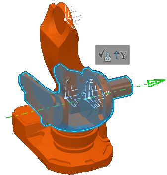
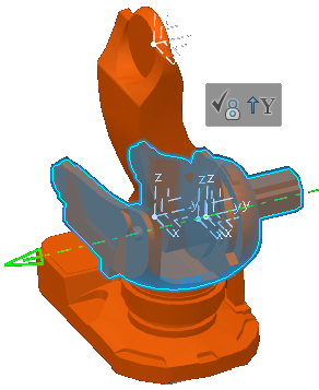
When the axis for the parent part is defined, the child part is snapped to the parent part by overlapping their respective axis systems.

A green dashed line passing through the joint location indicates the current joint axis (the Z-axis by default).
-
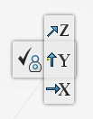
Pass the cursor over
 to display the available axes, and select a different one if needed.
-
Select the joint axis (green dashed line) to evaluate the joint sense.
An arrowhead appears at one end of the joint axis to indicate the current joint sense:
You can select the arrowhead to reverse the joint sense:
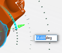
Pass the cursor over the moveable part. A manipulator appears and allows you to select and drag the part to jog the joint:

When jogging the joint with the manipulator, a scale displays the magnitude of the movement. Selecting the value in the scale displays an editor where an exact number can be entered:
-
Once the joint is defined, it can be created (or canceled) by selecting one of the following commands from the context toolbar.


Create a command joint. 
Create a non-command joint. 
Cancel the joint creation operation. - Select Define Kinematics to exit the command.
When a command or non-command joint is created, a mechanism is automatically created and the engineering connection is automatically considered by the mechanism.