-
Open the reference tool device.
-
From the Motion Controller section of the action bar, click Tool Part Grouping
 . .
The Tooling Part Grouping dialog box appears, and the root
device is automatically selected and appears as the Selected
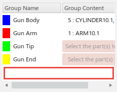
Resource. 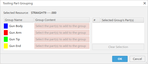 Four groups
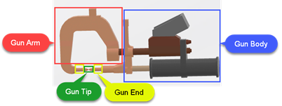
are available, Gun Body, Gun Arm,
Gun Tip, and Gun End. These correspond
to the groups defined in , and the color used for each group are the those specified in
Clearance Grouping Colors. Parts can be grouped in a
manner like the following:
-
You can select parts that are not yet assigned to any group, or modify the content of
already selected groups, by clicking the respective Group Content
cells and then selecting the parts.
Once selected, the parts are highlighted with that group’s color and are listed in the
Group Content cell. A prefix indicates the number of parts
selected.
-
To remove parts from a selected Group Content group, select the
corresponding parts in the Selected Group's Part(s) list and click
Clear Selection.
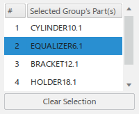
After a part is removed from a group, it will become uncolored again and is available
for selection in other groups.
-
You can start working on a different group by selecting the Group
Content cell for the desired group.
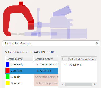
All geometry will become uncolored again, but you can only select parts that
have not already been assigned to a different group.
-
You can check at any time to see which parts have not been assigned to a group by
clicking in the empty space outside of any line from the left-side list widget (to remove
the selection).
All selected parts are highlighted with their respective group’s color, while
the un-selected ones remain uncolored. 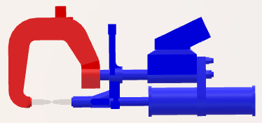 -
After assigning all parts to groups, all parts are colored based on the group they
belong to.
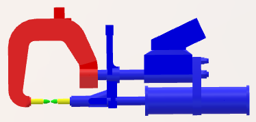
Once the groups have been defined, are saved and taken into account during clash
computing in order to apply the clearance values specified in based on the groups, context, and activation status.
|