Create Arc Trajectory Dialog Box | ||
| ||
General
- Name
- Displays the name of the current trajectory. The trajectory name can be edited here.
- Tool
- Displays the current weld gun.
When a tool is selected, the tool is highlighted in the work area and its selected TCP is indicated by an orientation Robot. When the tool selection or TCP changes, the highlight and compass are correspondingly updated.
Trajectory Management
This section provides the tools for creating, deleting and ordering trajectories.
Trajectories can be created via any of five different methods provided in the list.
- Tags
- Curves
- Surfaces Intersection
- Parts Intersection
- Reference Trajectory
Tags allows you to create the trajectory based on the selection of an existing tag group.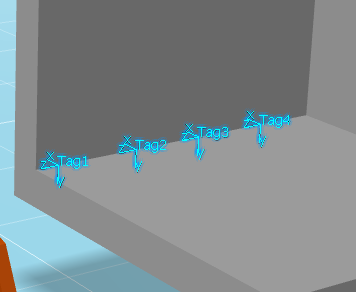
Curves allows you to create the trajectory based on the selection of a contour on geometry in the work area. You can also select a bead fastener from the tree, or a bead fastener's Localization object in the work area. 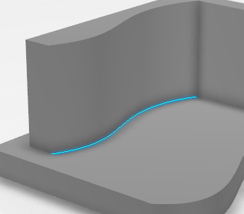
Surfaces Intersection allows you to create the trajectory based on the intersection of two surfaces selected in the work area
For Surfaces Intersection, select one or more base surfaces in the work area. 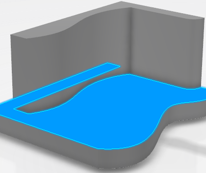
Each selection is added to Base Surface(s) in the Select Curves dialog box.
Click in Wall Surface(s) in Select Curves to highlight it before selecting one or more wall surfaces in the work area. 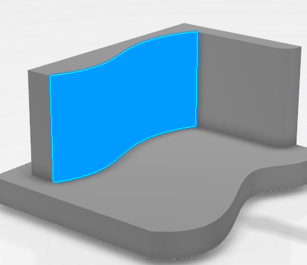
Each selection is added to Wall Surface(s) in Select Curves.
Parts Intersection allows you to create the trajectory based on the intersecting surfaces between two three-dimensional parts.
The first selected part is shown in the Select Parts dialog box as the Base Part, and the second becomes the Wall Part.
Reference Trajectory allows you to create the trajectory based on selecting an arc trajectory in a Curve operation.

- Click to create a new trajectory of the selected type.

- Click to delete one or more selected trajectories from the table.

- Click to move a selected trajectory up in the list.

- Click to move a selected trajectory down in the list.
Sampling tab
Sampling ![]() provides the following parameters that can be defined:
provides the following parameters that can be defined:
- Mode
-
Distance allows you to manually set the distance between two consecutive tags.
When Speed is selected, the distance is calculated based on the value specified for speed.
When Points is selected, the distance value is based on the number of points defined along the contour.
- Distance
- This option appears when Mode is set to Distance, and allows you to manually set the distance value.
- Speed
- This option appears when Mode is set to Speed, and allows you to manually set the speed value.
- Points
- This option appears when Mode is set to Points, and allows you to manually set the number of points.
- Sag
- This option defines the distance between the two consecutive points based on the line curvature that you set.
Offset tab
Offset ![]() provides the following parameters that can be defined:
provides the following parameters that can be defined:
- Start Length
- Allows you to set an offset from the beginning of the trajectory.
- Stop Length
- Allows you to set an offset from the end of the trajectory.
- Base Offset
- Allows you to define an offset distance from the base.
- Wall Offset
- Allows you to define an offset distance from the wall.
Orientation tab
Orientation ![]() provides the following parameters that can be defined:
provides the following parameters that can be defined:
- Roll
The wire roll is an angle measured about the electrode wire.
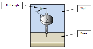
- Base
The base angle is the angle of the torch or electrode wire with respect to a user defined reference (base) surface.
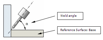
The base angle can be defined as Absolute, Relative to base or Base/Wall bisector.
- Rake
The rake angle is the angle measured with respect to the travel direction (Y-axis).
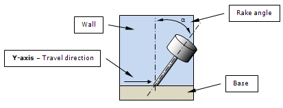
The rake angle can be defined as Absolute, Relative to base or Base/Wall bisector.
Tags tab
Tags ![]() lists all of the current tags in a table that indicates Type, Base, Rake, Roll, and Nominal Base for each tag
lists all of the current tags in a table that indicates Type, Base, Rake, Roll, and Nominal Base for each tag
Selecting a tag in the list has the same effect as selecting the tag in the work area. When a weld tag is selected, the Arc Weld orientation Robot is snapped to the tag and the context toolbar is displayed. When a via tag is selected, the orientation Robot snaps to the tag in the work area. This method of selection is useful in situations where tags are nearly overlapping and difficult to select in the work area.
Approach/Depart tab
Approach/Depart ![]() provides the following parameters that can be defined:
provides the following parameters that can be defined:
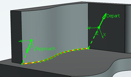
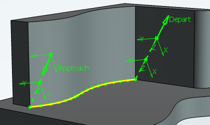
- Approach
-
When set to On, the Approach path appears in the trajectory as shown above.
- Depart
When set to On, the Depart path appears in the trajectory as shown above.
- Distance
- Sets the distance values for approach and depart.
- Points
-
Allows you to define the number of points along the Approach and Depart paths.
Flare Points tab
Flare Points ![]() provides the following parameters that can be defined:
provides the following parameters that can be defined:
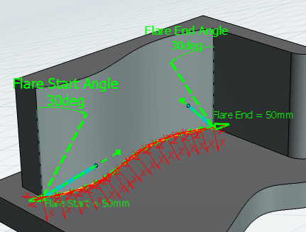
- Flare Start
-
When set to On, the flare start angle appears in the trajectory as shown above.
- Flare End
When set to On, the flare end angle appears in the trajectory as shown above.
- Distance
- Sets the distance values for the flare start and end angles.
- Angle
-
Allows you to define the angle value for the flare start and end angles.