Using a Weld Template Primitive File | |||||
|
| ||||
-
From the Arc section of the action bar, click Weld Template System
 .
You are prompted to select a robot.
.
You are prompted to select a robot. -
Click in the Base Surface box and select all surfaces that will
serve as base surfaces in the work area.
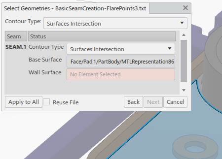
When there is more than one selection, Base Surface maintains a count of the number of surfaces selected.
-
Click in the Wall Surface box and select one or more wall
surfaces in the work area.
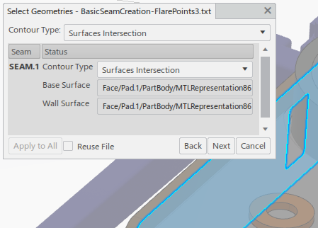
When there is more than one selection, Wall Surface maintains a count of the number of surfaces selected.
-
When all surfaces are selected, click Next.
A panel appears that is titled based on the HEADER line of the loaded primitive file. It lists the created seams and parameters that were used in the process of seam creation. Parameters are displayed among four tabbed pages as follows.

Free lists parameters that can be modified. 
Fixed lists parameters that are locked and cannot be modified. 
Globals lists those parameters that are not defined in the primitive file, but whose default values are used to create a trajectory or task. These values cannot be modified. 
WTS Display displays a section of the primitive file that was used to create the current seam. In the work area, a transient trajectory is created, and tags appear on the intersection of the selected surfaces.
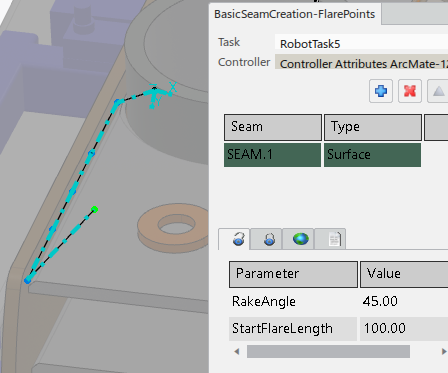
After the points of a transient trajectory are created, a reach status analysis is performed. Reachable points are displayed in green. Points can also be out of limits (yellow), unreachable (red) or in clash (blue).
- Optional:
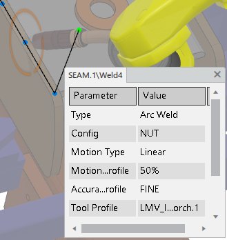
Select a point.
The robot moves to the point, and a panel displaying the properties of that point appears. The position, orientation and other motion properties of the points can be modified.
- Optional:
You can clone the seam and apply it to a different piece of geometry. The cloned seam has the same set of parameter values as the original seam.
- Click
 .
. - Select additional geometry as you did in Steps 4-7.
Once geometry selection is complete, the new seam is created and appears in the list.

- Click