About EndCut Extralength | ||
| ||
Edit Features Command - Change of Location Type
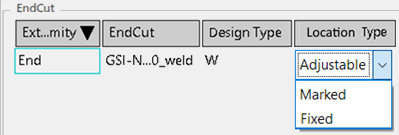
- In this case End Face fully uses, only
Adjustable and Marked in the list.

- In this case, End Face partially uses all the choices in the
list.
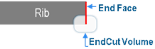
Manufacturing EndCut behavior based on Location Type
- Adjustable case - In case of Added Material / Fit-up /
RootGap / Overlength applies on the Start | End.
- Applied on Web: As below, regardless of volume type, the entire
volume moves as the margin values(A) apply.
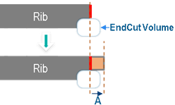
- End Face fully uses all the EndCuts volume.

A = Added Material [Start|End] Web - Fit-up [Start|End] Web – RootGap [Start|End] Web + Overlength [Start|End]. - End Face partially uses the EndCuts volume.

A = Added Material [Start|End] Web - Fit-up [Start|End] Web – RootGap [Start|End] Web + Overlength [Start|End]
- End Face fully uses all the EndCuts volume.
- Applied on Flange - EndCut volume does not move.
- Applied on Web: As below, regardless of volume type, the entire
volume moves as the margin values(A) apply.
- Fixed Case - In the case of Added Material / Fit-up /
RootGap / Overlength applied on Start |
End.
Applied on web: The EndCut volume does not move. If End Face partially uses the EndCut volume:
A = Added Material [Start|End] Web + Overlength([Start|End]) - Fit-up [Start|End] Web – RootGap [Start|End] Web. - Marked Case - In the case of Added Material / Fit-up /
RootGap / Overlength applied on Start |
End.
Applied on web: EndCut volume does not move but marks on the web.
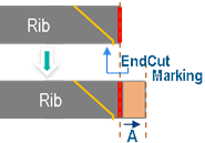
A = Added Material [Start|End] Web + Overlength([Start|End]) - Fit-up [Start|End] Web – RootGap [Start|End] Web.
Workshop Document
- Profile Fab Sketch - Geometry appeared in 3D(In-Process Models) reflects in the drawing.
- Profile Content in XML:
New Node EndCuts adds under Manufacturing as in this scenario.
- EndCuts node is consisted of two EndCuts nodes.
- EndCuts node has these attributes:
- Side: Start or End must be the value. This is based BSU Start/End location.
- LocationType: value fills as
Adjustable, Marked, or
Fixed.

Plate Data XML - These nodes add for each MarkedEndCut.
New marking nodes added for each MarkedEndCuts.
- This marking node has below attributes:
- Type: Displayed as MarkedEndCut.
- Closed: Displayed as FALSE.
- Side: Displayed as NearSide.
- This node has <Geometry> and <Graphic> nodes in it. And filled by the logic as other marking nodes.