About Supporting Beam Fabrication | ||
| ||
Feature Creation
The following features support: BSU, Outer Contour, Attachment Line (On connected Plate), Alignment Line, Positive Margin, Edge Preparation, Manufacturing End cut, IBC, Feature transfer.
- BSU and Outer Contour Features: generated during update IPMs.
- Feature creation with Profile Rules:
- Features create on the beam after reading the Profile Rules defined in the PRM.

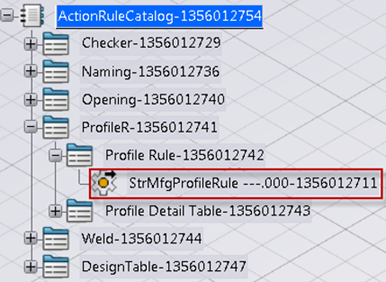
- These rules enable you to create the following features on the beam:
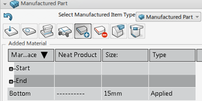
- Positive margins on the free faces of the beam (web start, web end, flange start, flange end, bottom).
- Negative margins on the free faces of the beam (web start, web end, flange start, flange end, bottom).
- Edge preparations on the free faces of the beam (web start, web end, flange start, flange end, bottom).
- Features create on the beam after reading the Profile Rules defined in the PRM.
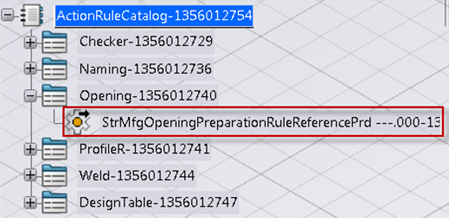
- Opening Rules:
Opening preparation completes on the profile as per the rule defined in the PRM.
- Feature creation with Weld Rules: SDD supports the following types of
welds, which involves a beam.

- Butt-Beam-Plate
- In this case, the attachment line creates on the plate and the alignment creates on the beam.
- Also, depending on the weld rules, cutting features like edge prep, positive
margin, negative margin then places on the beam face, which has limits.
- Tee-Profile-Profile
- In SDD, if a beam is created using the Beams and Plane
option, then the weld type between them is of type
Tee-Profile-Profile.

- In this case, attachment line + alignment creates on two vertical profiles (SFE/Stiffener/Member).
- And, the alignment line creates on the horizontal beam.
- In SDD, if a beam is created using the Beams and Plane
option, then the weld type between them is of type
Tee-Profile-Profile.
- Butt-Profile-Profile
- When a beam is created using the option Point to Point, then there is a possibility that the weld type would be Butt-Profile-Profile.
- In this case, attachment line + alignment creates on two vertical profiles (SFE/Stiffener/Member).
- And, the alignment line creates on the horizontal beam.

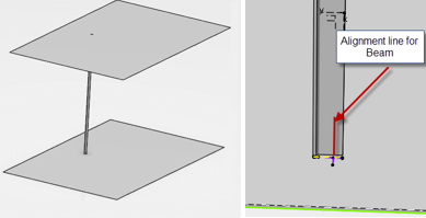
- Tee-Profile
- When a beam welds to an underlying plate, then this scenario arises.
- Attachment line + alignment line creates on the plate.
- Alignment line creates on the beam.
- Also depending on the weld rule, cutting features create on the bottom face.

- Butt-Beam-Plate
- Features created on the curved beam transfers onto the flattened beam.
- Roll lines generate on rolled beams.
- IBC generates for bent beams.
- Overlength creates on beams.


Feature Edition
- BSU is edited by changing to the BSU tab page.
- In the same tab page, the cutting length.

- The attachment line marked side and marking side can manipulate.
- Opening preparation for beams can edit through the opening preparation tab page.
- End cuts applied on the beam are in the end cut tab page.
- Margins can edit.
- If required, edit the Edge prep.
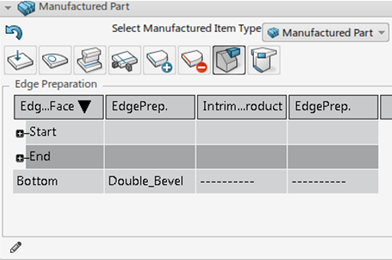
Workshop Documents
- Profile sketch generates for beams.
- Profile XML and IBC XML generate separately.
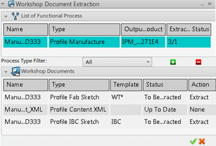
- A generated XML.

