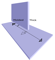
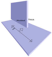
About Attachment Line Showing Thick and Molded Traces of Pilot Part

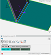
You can activate of this variable, to see Attachment lines created on both sides of the Marking body (Pilot Plate / Profile) part.

The following topics discuss:

This page discusses:

PRM Setup

  • Existing Weld Rule enhances to return the option to generate an Attachment line on one or both sides.
  • Input to weld rule is Weld feature. Using this, to retrieve the connected objects.
  • Based on Pilot Parts parameters (thickness, material etc.) you decide whether to create an Attachment line with both representation or single representation.

The keyword and return values from the rule are as follows:

  • Keyword: ShowBothRepresentationForAttachmentLine
  • Value:
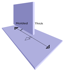
    • False → Single representation <default>.
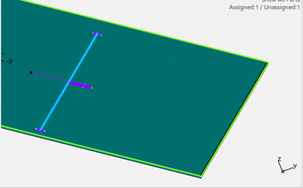
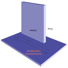
    • True → Both representation.

The value returned by the rule is referred to during Update IPM. By default, only single representation creates.

User Interaction

Update IPM

  • After Part planning and Weld Planning, click Update IPM to generate Manufacturing features.
  • Based on the rule definition, Attachment line with Single Representation or Both Representation creates.


Edit Feature -

  • Creation of Attachment Line
    1. Assembly Selection: Select Parent Assembly Process. Select Fastener Process as Reference Object. If the rule returns ShowBothRepresentationforAttachmentLine = false, then a Single Representation creates.

      If the rule returns ShowBothRepresentationforAttachmentLine = true, then Both Representations create.

    2. Single Plate selection: Select Plate and switch to Attachment line tab. Click on + to add attachment line. Select the Pilot Part Process and click OK.

      By default the Attachment line with Single Representation creates. No Weld Rule executes in this operation. Generation of Attachment line with Both Representation does not support this interaction.

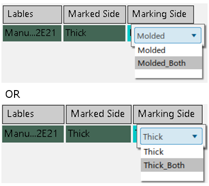
      Manually edit the Representation type to have Both Representations under the Marking Side column.

  • Edition of Attachment Line

    A Combination on the Attachment Line tab frame on the Marking Side is available. Select one/ multiple row in the List of Attachment lines. Click the Combination. Result: For Selected attachment lines having Single representation, the representation changes to Both representation type.

    Note: If in your selection, the Attachment line has Molded and Thick for the Marking side, then the Combination list does not display. In general, for given selection, if the selected attachment line list has uniform Marking side value, only then the corresponding Combination populates.

    Purpose of existing Change Marking Side is to switch between the following type of Marking Side values:
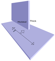
    FROM TO
    Moulded

    Thick

    Molded_Both

    Thick_Both

    Thick

    Moulded

    Thick_Both

    Moulded_Both

    This change of values impacts the orientation of the MTO and Alignment line accordingly.

    Purpose of Combination List in Marking Side column helps to change representation type between the following values:

    FROM TO
    Moulded

    Moulded_Both

    Molded_Both

    Moulded

    Thick

    Thick_Both

    Thick_Both

    Thick

    This change of values does not impact the orientation of the MTO and Alignment line.

Plate XML Entries

Launch workshop document generation and select the Plate on which the Attachment line with both representation creates. Click OK to generate drawing and Plate XML. The result of plate XML has an entry for the additional line created for the Attachment line.