Changing View Orientation for Plate Fab Sketch | ||
| ||
From Customizing Preferences , Plate Fab Sketch Orientation, select the option for Plate/Panel sketch Orientation.
From Preferences +X, +Y, + Z, -X, -Y, -Z are directions from the Reference Plane System assigned in Common Geometry Resource->Common Geometry Reference in Data Setup.

Top, Bottom, Right, Left are the direction in the Plate fab sketch.
Depending on the Plane of Plate/Panel, you can select Sketch Orientation and use options based on the Plate/Panel fab sketch getting oriented.
Example:
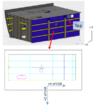
The Plate lies in the XZ plane of the CGR. Projection plane is the same as the current behavior of the WD extraction command. The drawing generates by projection from the Z axis of the BSU on the BSU plane.
For this drawing, +Z of CGR points to the bottom of the sketch
Select orientation of the sketch with respect to the global orientation of CGR. For this plate on the XZ plane, select which direction of the CGR lies on which side of the sketch.
For example, you can choose the +Z as TOP for this plate on the XZ plane. In this case, the drawing rotates so the +Z direction of the CGR corresponds to the TOP of the sketch.
This shows the modified orientation of the sketch when selecting +Z as TOP for the plate on the
XZ plane. 
Text flipping:If selecting Auto Flip for text for the power copy created in administrative mode, the text automatically flips in the drawing according to the orientation.