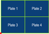
Using Multiple Shrinkage Parts for an Assembled Panel | ||
| ||
-
From the Authoring section of the action bar,
select Shrinkage Parts and click Edit
Features
 .
There is a Input Reset
.
There is a Input Reset and Define Axis origin
 in Outer Contourtab page of Edit
Features to support the common Axis Origin Point
creation.
in Outer Contourtab page of Edit
Features to support the common Axis Origin Point
creation. 
-
Click Define Axis origin
.
The Define Common Axis Origin dialog appears. This provides the common origin point creation and updates the shrinkage compensation parameter.
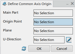
- Main Part – The part, which common Axis Origin is selected. Rep instance title of shrinkage resulting product displays.
- Origin Point – Common Origin Point for the multiple shrinkage parts. Select a vertex at the Outer Contour.
- Plane – Common Plane for multiple shrinkage parts. It is based on the Main Parts Burn Side Up XY plane.
- U-Direction – Direction based on Main Parts
X direction. You are able to replace the line with sketch
line using Sketcher
 .
. - Sketch - Launch the Sketcher
application. U-Direction is changeable
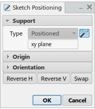
with the created sketch line. If required, click Sketch and the
Sketch Positioning dialog starts. The selected plane at
Plane editor on Input Define dialog is
established by default.
Create a straight line on Sketcher and select Exit App. The line (Sketch Line1) is established for U-direction input.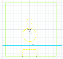
- Initialization - Initializes all values on the Define Common Axis Origin dialog.
-
Select a vertex at the outer contour features for Axis
Origin
Based on the origin point, Main Part, default Plane and default U-Direction automatically define.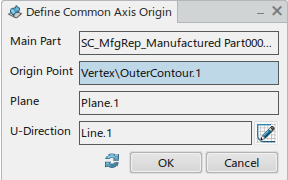
-
If required, click Sketch. Create a straight line on Sketcher and
select Exit .
The line (Sketch Line1) is established for U-direction input.

-
Click Edit Impacting Object.
In Edit Impacting Object dialog, pilot parts are listed to compute for the impacting direction.

The dialog box provides two arrows for U and V to put all items of each column to Remaining column. The decision for U and V impacting objects is applied to each attachment line on shrinkage parts. -
Update the ratio value of elements.
The ratio value update applies to all elements in the list.
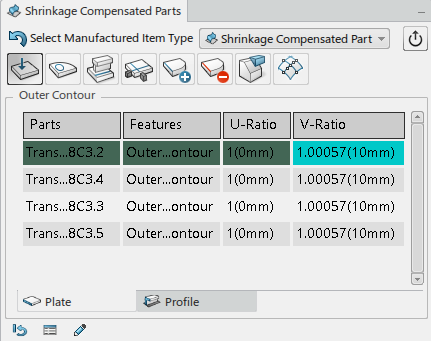
The common Axis Origin, the surfaces update as an assembled surface.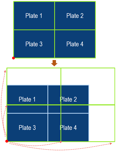
To re-establish the input parameters, Input Reestablish provides to make all parameters initial.
If Common Axis Origin or shrinkage parameter change is required, you must initialize the parameters and then establish a common Axis Origin again.
When selected, a warning message is displays. Selecting Yes, the re-establish proceeds.
The ratio value of shrinkage part elements is established for 1.
Main Part, Origin Point, Plane, and U-Direction does not have any input parameters.
