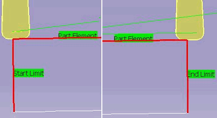
Groove Insert Positioning on Start and End Limits | ||
| ||
IN/ON/OUT Setting and Compensation Number
The IN (1)/ON (2)/OUT (3) setting on the Start/End Limits is represented in the figure
below (the arrow represents the direction of tool motion).
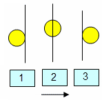
The tool compensation number (P9 (1)/P9R (2)) on the insert
geometry is represented in the figure below

The behavior is illustrated in the figures below. This is applicable in general for different Location and Orientation strategy parameters.
For all cases, following is the behavior for different modes of the Limit elements:
- IN: Positive offset value moves limit element opposite to the direction of machining. Negative offset value moves the limit element in the direction of machining.
- ON: Offset value has no effect in this mode. Limit element location is not changed in this case.
- OUT: Positive offset value moves limit element in the direction of machining. Negative offset value moves the limit element opposite to direction of machining.
The following images shows the above behavior for P9 and P9R compensations:
- P9 with IN setting on the Start/End Limits and no
offset value for Start/End Limit:
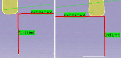
- P9 with IN setting on the Start/End Limits and
positive offset value for Start/End Limit:
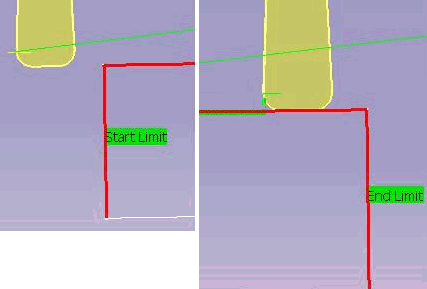
- P9 with IN setting on the Start/End Limits and
negative offset value for Start/End Limit:

- P9R with IN setting on the Start/End Limits and no
offset value for Start/End Limit:
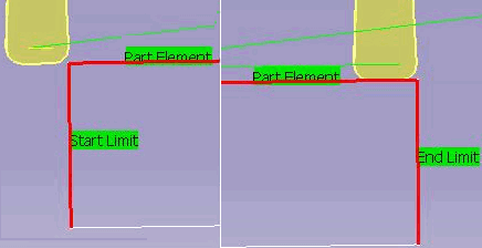
- P9R with IN setting on the Start/End Limits and
positive offset value for Start/End Limit: P9R with IN setting on the Start/End Limits and no
offset value for Start/End Limit:

- P9R with IN setting on the Start/End Limits and
negative offset value for Start/End Limit:
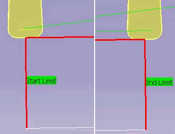
- P9 with ON setting on the Start/End
Limits:
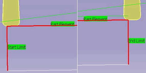
- P9R with ON setting on the Start/End
Limits:
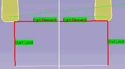
- P9 with OUT setting on the Start/End Limits and no
offset value for Start/End Limit:
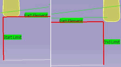
- P9 with OUT setting on the Start/End Limits and
positive offset value for Start/End Limit:
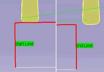
- P9 with OUT setting on the Start/End Limits and
negative offset value for Start/End Limit:
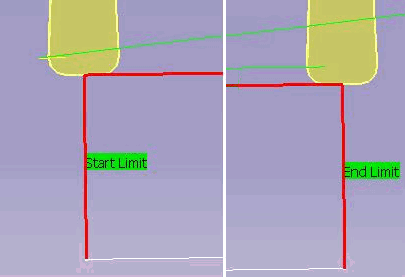
- P9R with OUT setting on the Start/End Limits and
no offset value for Start/End Limit:

- P9R with OUT setting on the Start/End Limits and
positive offset value for Start/End Limit:

- P9R with OUT setting on the Start/End Limits and
negative offset value for Start/End Limit:
