Automatic Computation of Tool Parameters

The calculation of the Tool Parameters (Setup angle and Tool Inversion) is done automatically and is considered internally for computing a tool path. This describes various scenarios.

This page discusses:

Definition of Tools

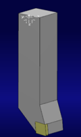
For physical mill-turn machines, the tools/holders/shanks are defined as assemblies as previously where there was no physical definition.

Each tooling component has a base and a mount axes system by which the mount axis system of one child component is matched with the parent component to assemble the two.


Methodology of the Assembly for Mill-Turn Operations

The Methodology for Assembling adaptors for Mill-Turn Operations

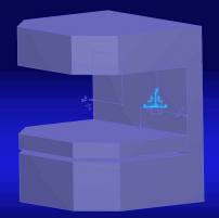
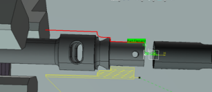
An adaptor, a machine accessory which was created in machine builder with its base axis shown.


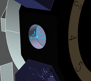
Mount axis(index 4) is defined on the turret. Make sure that the axes systems are right handed, otherwise there is unpredictable results.


Mounting the Adaptor onto the Turret Mount Location

This describes mounting the adaptor on the turret mounting location.


In the Machine configuration view, right-click to select the appropriate mount location on the turret.

This shows the list of the machine accessories. Select the adaptor required. Mount the adaptor.

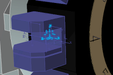
The mount axis of the turret and the base axis of the machine accessory is matched. Selection of Mount 4 highlights this matched axis.


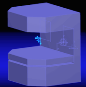
Once the adaptor is mounted, two mounting axis TMP A and TMP B are defined.

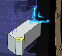
If TMP B is selected, by right-clicking and selecting Assign from the contextual window we see a list of tools which is assigned (mounted) on the machine accessory. From the list, we select T1. The tool assembly is a left handed external tool. We see the mount axis on the tool assembly created in Setup. The axis is a right handed system.

Mounting the tool assembly of the adaptor

This shows to mount the tool assembly of the adaptor.

Here the mount axis of Tool assembly T1 and the base axis of the machine accessory is matched. Selection of TMP B highlights this matched axis.

Usage of a Tool in a Turning Operation

This shows how the mounted tool can take part in machining.

The Tool which is defined on Mount location 4 is index to participate in machining as oriented as shown.
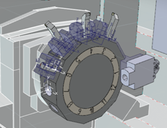
If the tool orientation is observed, it matches this. But the orientation is not the desired one and the toolpath is not acceptable.

We need to add a tool invert to get the desired orientation. In the dialog box, under Geometry tab, select to activate Tool Inverted. If we update positions, the tool orientation is changed in the configuration manager.

Here is how the mounted tool can take part in machining after applying the tool invert parameter. The Tool which is defined on Mount location 4 is indexed to participate in machining as oriented as shown.
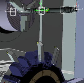
Compute the toolpath again and the tool orientation and hence the toolpath is the desired one.
Axis systems of turning tool assemblies

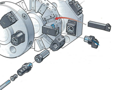
It is important to understand how the system creates the mount axis systems on the various turning tool assemblies which helps you to create the correct mount points on the turret and machine accessories.

Following are the tool assemblies available in turning

  • External turning tool assembly
  • Internal turning tool assembly
  • External groove tool assembly
  • Frontal groove tool assembly
  • Internal groove tool assembly
  • External threading tool assembly
  • Internal threading tool assembly

Mounting conventions

This show the different types of mounting conventions for External and Internal.

  • External/frontal turning tools - The orientation of the axis is as defined in the turning plane (2). Mount axis (1)should be defined as below(When indexed to the turning plane).


    External tool hand: Left

    External tool hand: Left


    External tool hand: Neutral

    External groove tool hand: Left

    External groove tool hand: Right

    External groove tool hand: Neutral

    External thread tool hand: Left

    External thread tool hand: Right

    Frontal groove tool hand: Left

  • Internal turning tools - The orientation of the axis is as defined in the turning plane (2). Mount axis (1) should be defined as below(When indexed to the turning plane)


    Internal turning tool hand: Left

    Internal turning tool hand: Right


    Internal groove tool hand: Left

    Internal groove tool hand: Right

    Internal thread tool hand: Left

    Internal thread tool hand: Right