Geometry Parameters | ||
| ||
Geometry Selection for Sequential Turning
![]()
You can select lines, curves, and edge elements as check and drive elements. Points can also be selected as checks. Selected elements must be located in the plane defined by the machine spindle axis and radial axis.
The following cases summarizes how the tool is positioned with respect to a check element depending on the To/Past modes and negative/positive offset values.
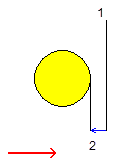
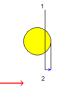
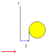
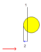
1 is Check 2 is Offset in these examples.
Case 1: Check Mode: To and Positive offset
Case 2: Check Mode: To and Negative offset
Case 3: Check Mode: Past and Positive offset
Case 4: Check Mode: Past and Negative offset