Cutter Compensation with Finish Turning Operations | ||
| ||
Cutter Compensation Options
The Cutter Compensation: None / On / Reverse option is proposed for finish operations. If this option is set to On or Reverse, the NC output can include CUTCOM instructions in the APT or clfile output for cutter compensation (CUTCOM/RIGHT, CUTCOM/LEFT, CUTCOM/OFF).
- On: CUTCOM/RIGHT instruction generated if tool is to the right of the tool path and CUTCOM/LEFT if tool is to the left of the tool path
- Reverse: CUTCOM/RIGHT instruction generated if tool is to the left of the tool path and CUTCOM/LEFT if tool is to the right of the tool path.
- None: If the option is set to None, no CUTCOM instruction is included in the NC data output.
A CUTCOM instruction is always generated before a linear trajectory in order to be active on that displacement:
- for a tool approach, the instruction CUTCOM/RIGHT or CUTCOM/LEFT is generated at latest in the approach phase of the trajectory, before the lead-in and on a linear trajectory.
- for a tool retract, the instruction CUTCOM/OFF is generated at earliest in the retract phase of the trajectory, before a linear trajectory or the last point of the operation.
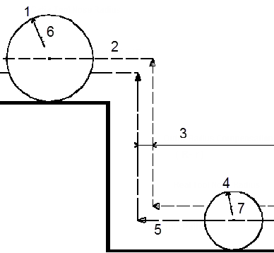
The figure below illustrates a Profile Finishing operation that has circular
lead-in and linear lift-off. 
- 6- Lift-off
- 7- Lead-in
If the cutter compensation is set to ON, the CUTCOM instructions are generated as follows:
- CUTCOM/RIGHT is generated at point 1, before the tool motion to point 2. Note that if lead-in was linear, CUTCOM/RIGHT is generated at point 2, before the tool motion to point 3.
- CUTCOM/OFF is generated at point 4, before the tool motion to point 5. Note that if lift-off was circular CUTCOM/OFF get generated at point 5, before the linear retract motion.
Set Cutter Compensation Options
The computed tool path corresponds to the trajectory followed by the output point of the tool used in the Generic Machine.
- Set Cutter Compensation to On in the following
cases:
- the cutter radius of the actual tool used for machining is greater than the radius of the programmed tool and a positive compensation value is entered at the NC machine.
- the cutter radius of the actual tool used for machining is less than the radius of the programmed tool and a negative compensation value is entered at the NC machine.
- Set Cutter Compensation to Reverse in the following
cases:
- the cutter radius of the actual tool used for machining is less than the radius of the programmed tool and a positive compensation value is entered at the NC machine.
- the cutter radius of the actual tool used for machining is greater than the radius of the programmed tool and a negative compensation value is entered at the NC machine.
We recommend that you should program with tools whose cutter radius is greater than those that can actually be used on the machine. This helps you to anticipate tool/part collisions that may arise when cutter compensation is used.
If negative compensation values are allowed on the machine, set Cutter Compensation to On.
If negative compensation values are not allowed on the machine set Cutter Compensation to:
- On, if the tool actually used has a greater cutter radius than the programmed tool.
- Reverse, if the tool actually used has a smaller cutter radius than the programmed tool.
The figure below illustrates cutter compensation for profile finishing.

- Catia Tool Nose Radius
- Catia Tool Path
- Outer Radius Compensation (R- r)
- Real Tool Nose Radius
- Real Tool Path
- R
- r