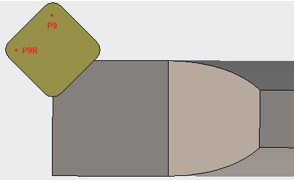
Conventions for Tool Assembly Turning | ||
| ||
General Considerations
The Machining Axis is always a direct axis system. For example, ZX defines a direct axis system with Z as the spindle axis and X as the radial axis.
Selected geometry (for example, Finish Profile Turning) is selected either in X+ or X-:
- the system figures out whether machining is in X+ or X- based on insert-holder orientation (as defined using set-up angle)
- depending on the options of the machining operation, several possibilities might exist (for example, Frontal machining). User option is then available (X+/X-) to specify what the system must do.
The output point definition is considered according to the X+/Z+ quadrant.
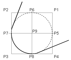
- Round, Diamond and Triangle Inserts
-
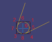
- Square Insert
-
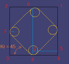
- Groove Insert
-
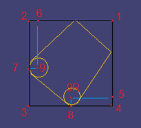
Examples below deal with horizontal lathe machine tool.
Insert Holder
Different settings of the setup angle, invert tool, and hand style parameters result in different configurations for positioning the tool.
Left Tool: Insert is visible and points to left: 
Inverted Left Tool: 
Right Tool: Insert is visible and points to right: 
Inverted Right Tool: 
Output Point
In the following figure reference is made according to the Spindle(2)/Radial(1) Axis (Z/X).

Spindle Rotary Direction
With a horizontal lathe machine tool the convention for spindle rotary direction defined in the Generic Machine dialog box is as follows: Looking into Z direction, Chuck and Jaws at your back.
Clockwise (R): 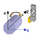
Counterclockwise: 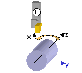
The following represent common settings:
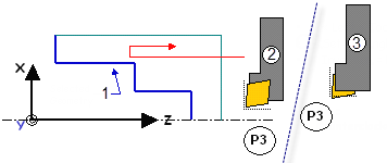
- Selected geometry
- L (Left Tool)
- Set-Up Angle = 0 deg.
- Inversion = NO
- Spindle = Counterclockwise
- or R (Right Tool)
- Set-Up Angle = 0 deg.
- Inversion = YES
- Spindle = Clockwise
180 degrees Set-up Angle
When setup angle is set to 180 degrees, machining takes places in X- as the system detects that this is what the tool can machine. Geometry is clicked X+ or X-.

- Selected geometry
- L (Left Tool)
- Set-Up Angle = 180 deg.
- Inversion = NO
- or R (Right Tool)
- Set-Up Angle = 180 deg.
- Inversion = NO
- L (Left Tool)
- Set-Up Angle = 180 deg.
- Inversion = YES
Direct Machining Axis
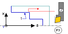
As the Machining Axis is always considered as being direct, the two situations below are the same. This corresponds to a rotation around the spindle axis.

- Selected geometry
- L (Left Tool)
- Set-Up Angle = 0 deg.
- Inversion = NO
- Selected geometry
- L (Left Tool)
- Set-Up Angle = 0 deg.
- Inversion = NO
Summary
The following figures summarize conditions for lathe tool assemblies.
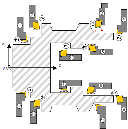
- L (Left Tool)
- Set-Up Angle = 0 deg.
- Inversion = YES
- R (Right Tool)
- Set-Up Angle = 0 deg.
- Inversion = NO
- L (Left Tool)
- Set-Up Angle = 0 deg.
- Inversion = NO
- R (Right Tool)
- Set-Up Angle = 0 deg.
- Inversion = YES
- L (Left Tool)
- Set-Up Angle = -90 deg.
- Inversion = NO
- L (Left Tool)
- Set-Up Angle = -90 deg.
- Inversion = NO
- L (Left Tool)
- Set-Up Angle = -90 deg.
- Inversion = YES
- R (Right Tool)
- Set-Up Angle = -90 deg.
- Inversion = NO
- R (Right Tool)
- Set-Up Angle = 180 deg.
- Inversion = NO
- L (Left Tool)
- Set-Up Angle = 180 deg.
- Inversion = YES
- L (Left Tool)
- Set-Up Angle = 180 deg.
- Inversion = NO
- R (Right Tool)
- Set-Up Angle = 180 deg.
- Inversion = YES
The figure below shows other settings for different output points.
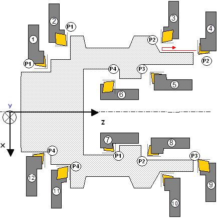
- L (Left Tool)
- Set-Up Angle = 180 deg.
- Inversion = NO
- R (Right Tool)
- Set-Up Angle = 180 deg.
- Inversion = YES
- L (Left Tool)
- Set-Up Angle = 180 deg.
- Inversion = YES
- R (Right Tool)
- Set-Up Angle = 180 deg.
- Inversion = NO
- R (Right Tool)
- Set-Up Angle = -90 deg.
- Inversion = NO
- L (Left Tool)
- Set-Up Angle = -90 deg.
- Inversion = YES
- R (Right Tool)
- Set-Up Angle = -90 deg.
- Inversion = NO
- R (Right Tool)
- Set-Up Angle = -90 deg.
- Inversion = NO
- R (Right Tool)
- Set-Up Angle = 0 deg.
- Inversion = YES
- L (Left Tool)
- Set-Up Angle = 0 deg.
- Inversion = NO
- L (Left Tool)
- Set-Up Angle = 0 deg.
- Inversion = YES
- R (Right Tool)
- Set-Up Angle = 0 deg.
- Inversion = NO
