About the Jog Dialog Box

The Jog dialog box is partitioned into four logical sections: Cartesian, Joint Values, Home Positions, and Options.

This page discusses:

Cartesian

Coordinates
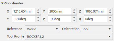


X The current Tool Center Point (TCP) X value with respect to the selected Reference.
Y The current TCP Y value with respect to the selected Reference.
Z The current TCP Z value with respect to the selected Reference.
Y The current TCP Yaw value with respect to the selected Reference.
P The current TCP Pitch value with respect to the selected Reference.
R The current TCP Roll value with respect to the selected Reference.
Reference Specifies the reference frame in which the Tool Center Point (TCP) coordinates are defined.
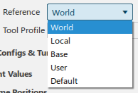
Orientation Specifies the orientation of the Tool Center Point.

Tool Profile Specifies the tool profile associated with the robot.

Configs & Turns


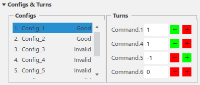
Configs lists all available configurations and their status.

Turns lists the current turn values for the selected configuration. Each turn value can be incremented (+) or decremented (-). The controls are color coded to indicate whether the resulting joint value will be inside (green) or outside (red) of specified travel, soft, and caution zone limits when clicked.
Joint Values

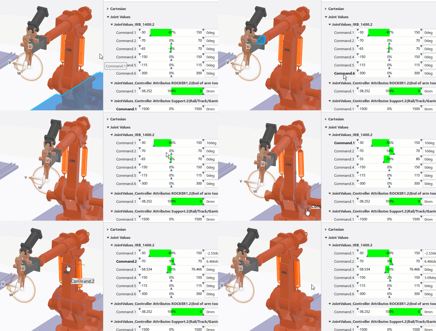
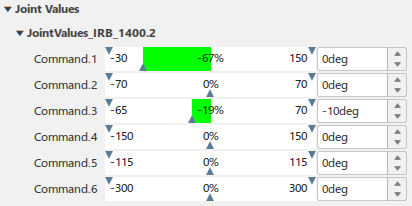
This section consists of a slider bar, numeric input field, and pair of increment/decrement buttons for each command of the mechanism.

When the Jog dialog box appears, the slider bar and numeric input field display the current value of each command.

  • The slider bar can be used to vary the command value between the minimum and maximum travel limits. The joint values are displayed graphically as bars. The limits are displayed on these graphical bars (for example, -90 to 90 in Joint.2, above). When a joint value exceeds a limit, the bar becomes red and text in the bar shows by how much the limit has been exceeded (for example, 11% in the example below). Joint movement within limits appears in green.

  • The numeric input field can be used to key in the command value given the default units for translation and rotation.
  • The increment/decrement spinners can be used to increase/decrease the command value in discrete steps. The step-size is controlled by the two values entered in the Steps section.
  • The parts of a joint that are affected by a command are prehighlighted when hovering over the command names.


Home Positions

Home Positions provides a list of defined home positions for each controlled resource.

Options

Step Size

This section defines the TCP and Joint linear and angular step-sizes that are used in the increment/decrement functions.

Snap Options

Select to Control Orientation and Control Location with respect to the current selection.

Display


Highlight Parts

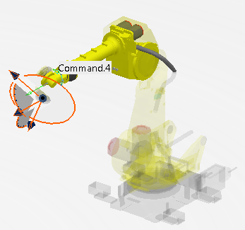
You can highlight the device parts that participate in the joint that is jogged by de-emphasizing the rest of the device.

When selected, Highlight Parts emphasizes those parts that are specific to the jogged joint by making other, unrelated parts transparent. In the example below, the parts associated with Command.4 are highlighted, and the remainder are transparent in appearance.


Note: Parts associated with noncommand joints are also highlighted when a command joint is jogged if they have kinematic relations that are defined as a function of that command joint.

Immediate

This check box specifies the protocol for updating the mechanism model.

  • When selected, the Jog mechanism is in immediate mode and each change to a command value is applied immediately to the model.
  • When not selected, the Jog mechanism is in deferred mode and multiple command values can be modified before being applied to the model.

Clicking Apply Position forces all modifications to be applied.

Every time you click Apply Position, you can use Undo to go back from that position. Once you have used Undo to go back one position, you can use Redo to move forward.

Continuous Update

You can enable the joint value bars to update as the robot motion is jogged.

  • When selected, the joint value bars are continuously updated as the robot motion is jogged.
  • When not selected, the joint value bars do not update until the jog movement has stopped.

Show Only Motion Group Home Positions

When selected, the Home expander shows only the home positions of the current motion group. When not selected, all home positions are shown for each device.

Show Sectioned View

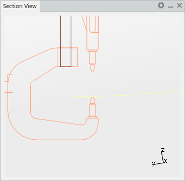
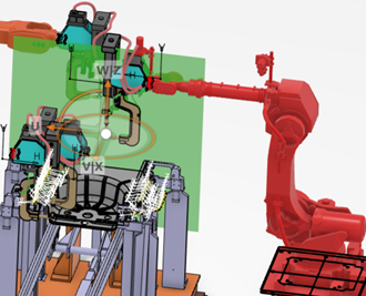
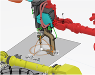
You can display a section view at the robot TCP in Jog.

A sectioned view is helpful when analyzing the reachability and the feasibility zones around the free axis associated with a target for one or more robots.

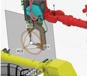
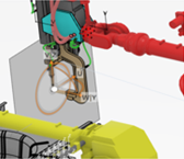
Select Show Sectioned View to display a new panel with the 2D Section View at the TCP.


Options are available by clicking Show Preferences in the dialog box titlebar.


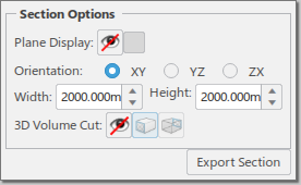
Plane Display

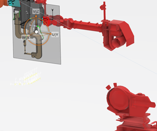
By default, the plane visibility in 3D is turned off. It can be enabled by clicking .


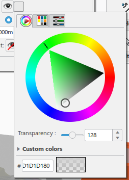
You can click the color swatch to define a custom color for the plane.


Orientation
The section cut plane can be based on one of the three available orientations. This setting impacts both the 2D panel and the 3D plane (if shown).
XY

YZ

ZX

Plane Dimensions
The size of the section plane determines what objects are sectioned. It can be modified either with the Width and Height options in the Section Options panel or, if the plane is visible in 3D, using its manipulators in the work area.
3D Volume Cut
You can activate the 3D cut, either front or back.
Hide/Show
Front cut
Back cut
Front volume cut

Back volume cut

Export Section

The resulting section can be exported as a 3D shape.


Lock Robot Base Joint

Note: This option appears only if the robot is mounted on a rail.

This option allows you to lock the base joint of a robotic system that includes a rail. When selected, the value of the robot’s base joint remains constant throughout the stage of task programming. Constraining the base of the robot can help with collision avoidance in tight spaces, or when dealing with cables and hoses attached to the robot by minimizing robot motion.

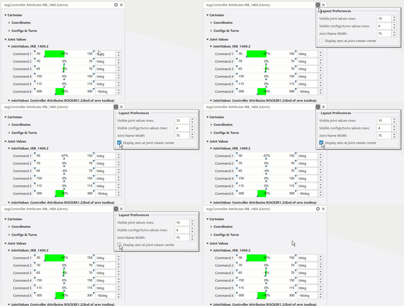
Layout Preferences

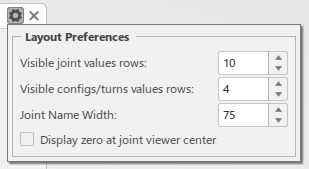
Layout Preferences allow you to specify how joints are displayed in the Jog dialog box.

Layout Preferences are by clicking Show Preferences in the Jog titlebar.

Visible joint values rows specifies how many rows of joint values are displayed before using a scrollbar to view additional rows.

Visible configs/turns values rows specifies how many rows of configs/turns are displayed before using a scrollbar to view additional rows. A setting of 8 displays all of the standard configurations of a robot.

Joint Name Width specifies the width of the joint name field.

Select Display zero at joint viewer center to display 0.0 at the center of the joint viewer rectangle.

Note: This option is applicable only when the minimum limit is less than 0, and the maximum limit is greater than 0.


Parallel Kinematics Machine Device Types

About

Parallel kinematics machine (PKM) robots feature multiple closed chains with passive (noncommand) joints.

During the forward kinematics of a PKM robot, noncommand joint values are automatically computed for the set of input forward kinematic command values (that is, the noncommand joint values depend on the command joint values).

A given set of command joint values can have multiple configurations of part positions. If the noncommand joints move to a different configuration, using Reset restores the command joint values but does not bring the robot to its original position. As a result, consider resetting the noncommand joint values whenever you use with Reset with PKM devices.