User Representation for the Tool | ||
| ||
Note:
To be supported by the collision check, the Rotary status of the user representation of the tool assembly must be set to Yes. See Management Representations The user representation must also comply with the following guidelines.
Constraints for Sketch Creation
For your tool assembly representation to be used in collision checking, comply with the following guidelines:
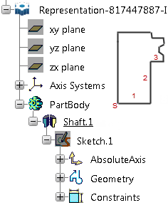
- The sketch profile must be constructed in the YZ plane.
- Its origin corresponds to the tool tip.
- H direction is that of Z axis.
- V direction is that of Y axis.
- The sketch must start from the V axis. (S)
- The sketch elements must be ordered in the counter clockwise
direction (1 . 2 . 3)

Supported Profiles
Sketch profiles must be described as a set of cylinders, spheres, conicals, or torus along the central axis of the tool. All other profiles are not supported, especially shapes defined along a local axis. If the user representation has an invalid profile, a warning message appears and the profile of the machining operation is taken into account during collision checking.
Notes:
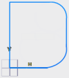
- Concave torus profile is supported.
- Tools with non cutting diameter are filled and transformed into a cylinder.
- For profiles with a concave cutter: the cutter concavity is not taken into account during collision checking. False collisions might be detected between the machined part and the concave area of the tool.
Examples of profiles:
 OK |  OK |  Not OK |