Define User Representation | ||
| ||
Representation
- Representation
-
Select the 3DPart or the 3DProduct that you can use to define the user representation of the tool component.
Note: If your representation contains more than one body, you cannot compute the profile, and a warning appears:Profile cannot be computed automatically. The User representation contains more than one body. Use the sketcher to define it.
This 3DPart is displayed in the work area. You can change the selected element, if you select Search Data Base
 again.
The selected 3DPart is now in the tree tool. This object must be in the session to allow the display and the selection.
Positioning
- Show Default Representations
-
You can change the positioning of 3DPart.
For easy positioning of the 3DPart, you can display the Default representation of the tool so you can select a better position.
You can choose to position base axis or mount axis of the 3DPart.
Example:
Before:

After:

You may need to add the definition of an angle to finalize the position of the 3DPart around the Z-Axis. This is important for the static representation.
Sometimes, you cannot define correctly the position of the 3DPart and you must define it in the data model, the axis that allows the positioning. You must do this step before referencing this 3DPart as a new user representation and after you select this axis to position on mount or base axis of default representation. In this case, the angle definition is unused.
Type
- Type
-
Define the cutting status of the tool. The options are: Cut or No Cut, if the 3DPart selected previously represents the cutting or no cutting part of the tool.
Example of Type: You create cut with a good position and define the profile.
3DPart RepInsertFraise_IN_WORK
- 807_1_3d_2564754
- xy plane
- yz plane
- zx plane
- INSERT
- INSERT_BODY
- Sketch.1
In this scenario, the 3DPart RepInsertFraise represents the cutting part of a face mill tool when it is turning.

If the selected representation describes both the cutting and no cutting part, you specify the breakdown to create two 3DParts.
3DPart from a step file or from database for rotating tool
5759_1_3d_138_IN_WORK
- 5759_1_3d_138_IN_WORK
- xy plane
- yz plane
- zx plane
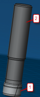
- INSERT_ BODY (1 on the image)
- Geometrical Set.1
- TOOLBODY_SOLID (2 on the image)
In this scenario, the 3DPart contains two bodies that represent the Cut and No Cut Part of an End Mill Tool when it is turning.
To Define the User Representation of this End Mill Tool, we have to extract the Cut and No Cut Part in two 3DPart and define for each of 3DPart the profile.
You can use this representation for a rotating tool and a static tool.

3DPart from database for a static tool.
60879610_0_Assembly
- 60879610_0_Assembly
- xy plane
- yz plane
- zx plane
- Axis Systems
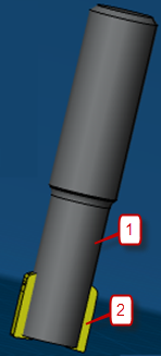
- NO_CUT (1 on the image)
- Geometrical Set.1
- CUT(2 on the image)
- Body.4
In this scenario, the 3DPart contains two bodies that represent the Cut and No Cut Part of an End Mill Tool static.
To Define the User Representation of this End Mill Tool, we have to extract the Cut and No Cut Part in two 3DParts. From these new 3DParts, we have to compute the representation when the tool is turning, and define the profile.
We use separately the representation static and rotary.

Positioning of 3DPart
Another point is important. This is the positioning of the 3DPart.
In fact, for the scenario (3DPart from a step file or from database for rotating tool), when you import the step representation provided by the Tool supplier, if you display the default representation, you can see the need to change the position.
R79-025A2552-16L
- R79-025A2552-16L
- DefaultCut_fbf-W04-2012Product
- DefaultNoCut_fbf-W04-2012Product
- 5759_1_3d_138_IN_WORK
- xy plane
- yz plane
- zx plane
- INSERT_BODY
- Geometrical Set.1
- TOOLBODY_SOLID
In this scenario, we have to position the origin axis of User Representation imported on the mount axis of the Default Representation.
The initial position may be OK, or the better position will be the base axis of the Default Representation.
Sometimes, the definition of the position will be more complex than a simple translation or rotation. For this, you first define an axis for the imported 3DPart. This makes it easy for positioning and after adding this representation to the tool.

Once you have defined a subset of part cutting or no cutting, you cannot modify the imported representation from the database and you cannot modify its positioning.
To define the Cut and No Cut Part:
If you select the Cut option, you can define in the viewer the cutting part of
tool (This is a single selection). After the selection, a new 3DPart appears
with the name defined and the selection command disabled.
The
 command cancels the selection and deletes the previous
3DPart created.
Proceed as the same way for the No Cut Part.
Variation of the editor depending on the type of a tool component.
For the Holder component, the way to define a new user representation is the same.
Some options are not available because there is no cutting part for the holder.
For the Type definition you have: No Cut.
For the Shank Lathe component of the lathe tool (no cutting part), you have the same definition for the Type. In addition, the lathe tool does not turn, we do not need to define a Rotary Representation, and therefore the frame for the use definition is not displayed.
For the Insert component of the lathe tool (cutting part), we do not display the Type definition, by default it is a Cut Part.
There is no need to define:
- The cut part on a subassembly because this element is stationary and any shank can reuse each inserted component.
- An angle of rotation in the positioning frame because the tool does not require it.
- A Rotary Representation, but unlike a shank component we need to test the sketch profile, and therefore use Check Profile.
Use
- Use
-
Define the use of this representation Rotary or Static.
The following rules of use are applied with Default, Static and Rotary Representation for Milling Tool:
User Representation Representation Display for tool Path Replay, Video Simulation Static Rotary Tool is staying Tool is turning Default Default X Priority to USER rep v.s. Default (hence Rotary) Rotary X Static Default X X Static Rotary The result of lathe tool is in the tool is staying column.
If you select Rotary (Check Profile) then OK, the validity of the representation will be checked.
To be supported by video and collision checking, the Rotary Representation must contain a sketch profile that complies with the following rules:
- You have constructed the sketch profile in the YZ plane.
- Its origin corresponds to the tooltip.
- H direction is that of Z axis.
- V direction is that of Y axis.
- The sketch must start from the V axis. (S)
- You must order the sketch elements in a counterclockwise direction.
If the representation is not valid, a warning message displays. Manufacturing Warning Invalid profile. The Profile is valid for video simulation a new profile is computed. After the validation warning message, a good sketch computes. The warning then adds this profile to the current representation. If you select the OK command, the result in the Manage Representation panel is:
Resource Product Name Type State Rotary Static To End Mill D 10_Product-149797886.1
To End Mill D 10_Product-149797886.1
UserRepCut_Product-149797886.1
UserRepCut_Product-149797886.1
Cut
No Cut
Normal
Normal
Yes
Yes
No
No
If you select Static then OK, this representation will be defined as a Static.
If you select Static and Generate Rotary then Ok, the Rotary Representation with the sketch profile used by video and collision checking will be created.