Reuse Programming - Update Geometrical Links Viewer | ||
| ||
Update Geometrical Links
- Status and Operation Name
- Shows the operation name and the status. When all the geometrical links of a feature or operation are defined, the link status light changes from red to green.
- Viewer
-
The Viewer displays all geometrical links defined by the feature template for a similar part. The link is highlighted in green if it is correctly defined, or in red if it has to be redefined. You can define links by selecting the label in the Viewer.
Note: When copying, the geometrical link defined on the published component has been created. You can identify this link by the color: the link is displayed in blue. If you select the label, you can redefine this link and the public link is lost.You can define what is displayed in the viewer by selecting one or several options using
 . You can select
Feature,
Strategy,
Geometry,
Macro or
Tool Path. You can also display the tool
path of an initial Machining Operation. All options are displayed by default,
with the exception of
Tool Path.
Viewing a Feature: All exported geometric features that are linked to the current operation, such as Simple Pattern and Offset Group, for example.
Viewing a Geometry: Additional geometry linked to the current operation.
Viewing a Macro: we distinguish the different Macro by the name of the link, which contains the Macro type. (Example: Approach/Plane)
Validate the command anytime. If the validation is confirmed, you have to manually complete the links to the new geometry.
- OK, Cancel
-
Validate anytime by selecting OK. If all geometries are not defined, you have to manually complete the links to the new geometry.
If you select CANCEL, or make UNDO after a validation, all components created in the new process are removed.

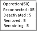
 which summarizes the states of geometrical links
for all Operations.
