PP Tables and Word Syntaxes - Axial Machining | ||
| ||
Examples
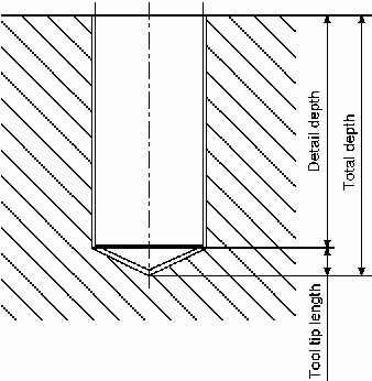
In the figures below:
- the detail depth (
MFG_DETAIL_DEPTH), total depth (MFG_TOTAL_DEPTH) and total depth up to the tool compensation point (MFG_TOTAL_DEPTH_COMP) are computed parameters. - the breakthrough distance (
MFG_BREAKTHROUGH) is a machining strategy parameter - the tool tip length is a geometric attribute of the tool
(
MFG_TL_TIP_LGTH).
The overall breakthrough is the breakthrough distance plus the tool tip length.
- Figure 1 showing Total depth without breakthrough
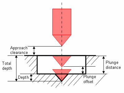
- Figure 2 showingTotal depth with breakthrough (The figures below show Depth mode
behavior on axial operations with chamfering machining):

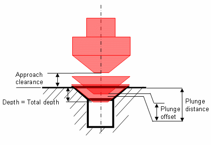
- Figure 3 showing Spot Drilling with Depth mode=By Tip
- Figure 4 showing Countersinking with Depth mode=By Diameter
Cycle Off Syntaxes
To close the NC Instruction generated by machining operations, a different Cycle off syntax is used for each type of operations.
- For the drilling operation, it uses NC_AXIAL_CYCLE _OFF
- For the turning operation, NC_LATHE_CYCLE_OFF
- And for the probing operation, NC_PROBING_CYCLE_OFF
By default (if the user defines nothing in the used PPtable) the NC_AXIAL_CYCLE_OFF, NC_LATHE_CYCLE_OFF and NC_PROBING_CYCLE_OFF instructions are defined by:
| NC Commands |
|---|
                      *START_NC_INSTRUCTION     NC_AXIAL_CYCLE_OFF
                      *START_SEQUENCE
                      CYCLE/OFF
                      *END
                      *END
|
                      *START_NC_INSTRUCTION     NC_LATHE_CYCLE_OFF
                      *START_SEQUENCE
                      CYCLE/OFF
                      *END
                      *END
|
                      *START_NC_INSTRUCTION     NC_PROBING_CYCLE_OFF
                      *START_SEQUENCE
                      CYCLE/OFF
                      *END
                      *END
|
NC_BACK_BORING
General parameters are as follows.
| NC Commands | Comments |
|---|---|
MFG_MO_TYPE
|
Defines the machining operation type. |
MFG_MO_IDENTIFIER
|
Specifies the machining operation name or identifier. |
MFG_PATTERN_NAME
|
Specifies the machining pattern name. |
Feeds and Speeds parameters are as follows:
| NC Commands | Comments |
|---|---|
MFG_FEED_APP_MODE
|
Specifies the approach feedrate mode (0: Value / 1: Rapid). |
MFG_FEED_APP_VALUE
|
Defines the approach feedrate. |
MFG_FEED_PLUNGE_MODE
|
Defines the plunge feedrate mode (0: Value / 1: Rapid). |
MFG_FEED_PLUNGE_VALUE
|
Defines the plunge feedrate. |
MFG_FEED_MACH_VALUE
|
Defines the machining feedrate. |
MFG_SPINDLE_MACH_VALUE
|
Defines the machining spindle speed. |
MFG_FEED_RETRACT_MODE
|
Defines the retract feedrate mode (0: Value / 1: Rapid). |
MFG_FEED_RETRACT_VALUE
|
Defines the retract feedrate. |
MFG_FEED_UNIT
|
Defines the feedrate unit. |
MFG_SPNDL_UNIT
|
Defines the spindle speed unit. |
Machining Strategy parameters are as follows:
| NC Commands | Comments |
|---|---|
MFG_CLEAR_TIP
|
Defines the approach clearance. |
MFG_CLEAR_TIP_2
|
Defines the second approach clearance. |
MFG_DEPTH_MODE
|
Defines the depth mode (1: Tip / 2: Shoulder). |
MFG_DWELL_MODE
|
Defines the dwell mode (0: None / 1: By revolutions / 2: By time). |
MFG_DWELL_REVOL
|
Defines the dwell delay in revolutions. |
MFG_DWELL_TIME
|
Defines the dwell delay in time units (seconds). |
MFG_LIFT_MODE
|
Defines the shift mode (0: None / 1: Linear coordinates / 2: Polar coordinates). |
MFG_XOFF
|
Defines a shift along X. |
MFG_YOFF
|
Defines a shift along Y. |
MFG_ZOFF
|
Defines a shift along Z. |
MFG_LIFT_ANGLE
|
Defines a shift angle. |
MFG_LIFT_DIST
|
Defines a shift distance. |
MFG_RETRACT_CLEAR_TIP
|
Defines a retract clearance. |
MFG_TOOL_COMP
|
Specifies the length number of current corrector. |
MFG_TOOL_COMP_DIST
|
Defines the distance between the position of the current corrector and the tool tip. |
MFG_TOOL_COMP_DIST_1
|
Defines the distance between the position of the first corrector and the tool tip. |
Geometry parameters are as follows:
| NC Commands | Comments |
|---|---|
MFG_DIAMETER
|
Defines the nominal diameter of the tool. |
MFG_NOMINAL_DIAMETER
|
Defines the nominal diameter of the machined feature. |
MFG_BCK_BORE_VAL
|
Defines the back bore depth. |
MFG_JUMP_DIST
|
Defines the jump distance. |
Computed parameters are as follows (see Figure 1 and Figure 2 above):
| NC Commands | Comments |
|---|---|
MFG_DETAIL_DEPTH
|
Computes the hole depth that is effectively machined. |
MFG_TOTAL_DEPTH
|
Computes the total depth machined by the operation. This includes the hole depth, breakthrough, and tool tip length. |
MFG_TOTAL_DEPTH_COMP
|
Computes the total depth machined by the operation up to the tool compensation point selected for the operation. This includes hole depth, breakthrough, and tool tip length up to the compensation point. |
MFG_CMP_DWL_TIME
|
Computes the dwell delay (in time units of seconds): this parameter is computed if dwell mode is set to 'revolutions'. Otherwise, the dwell time is returned as is. |
MFG_CMP_OFFSET
|
Computes the offset. |
MFG_CMP_ANGLE
|
Computes the shift angle. This parameter is computed if Shift mode is set to 'Linear coordinates'. Otherwise, the Shift angle is returned as is. |
By default, the syntax is
CYCLE/BORE,%MFG_TOTAL_DEPTH,%MFG_CLEAR_TIP
NC_BORING
General parameters are as follows:
| NC Commands | Comments |
|---|---|
MFG_MO_TYPE
|
Defines the machining operation type. |
MFG_MO_IDENTIFIER
|
Specifies the machining operation name or identifier. |
MFG_PATTERN_NAME
|
Specifies the machining pattern name. |
Feeds and Speeds parameters are as follows:
| NC Commands | Comments |
|---|---|
MFG_FEED_APP_MODE
|
Specifies the approach feedrate mode (0: Value / 1: Rapid). |
MFG_FEED_APP_VALUE
|
Defines the approach feedrate. |
MFG_FEED_PLUNGE_MODE
|
Defines the plunge feedrate mode (0: Value / 1: Rapid). |
MFG_FEED_PLUNGE_VALUE
|
Defines the plunge feedrate. |
MFG_FEED_MACH_VALUE
|
Defines the machining feedrate. |
MFG_SPINDLE_MACH_VALUE
|
Defines the machining spindle speed. |
MFG_FEED_RETRACT_MODE
|
Defines the retract feedrate mode (0: Value / 1: Rapid). |
MFG_FEED_RETRACT_VALUE
|
Defines the retract feedrate. |
MFG_FEED_UNIT
|
Defines the feedrate unit. |
MFG_SPNDL_UNIT
|
Defines the spindle speed unit. |
Machining Strategy parameters are as follows:
| NC Commands | Comments |
|---|---|
MFG_CLEAR_TIP
|
Defines the approach clearance. |
MFG_DEPTH_MODE
|
Defines the depth mode (1: Tip / 2: Shoulder). |
MFG_BREAKTHROUGH
|
Defines the breakthrough distance. |
MFG_PLUNGE_MODE
|
Defines the plunge mode (0: None / 1: Tip / 3: Diameter). |
MFG_PLUNGE_TIP
|
Defines the plunge tip distance. |
MFG_PLUNGE_OFFST
|
Defines the plunge tip offset. |
MFG_PLUNGE_DIAMETER
|
Defines the plunge diameter. |
MFG_DWELL_MODE
|
Defines the dwell mode (0: None / 1: By revolutions / 2: By time). |
MFG_DWELL_REVOL
|
Defines the dwell delay in revolutions. |
MFG_DWELL_TIME
|
Defines the dwell delay in time units (seconds). |
MFG_TOOL_COMP
|
Specifies the length number of current corrector. |
MFG_TOOL_COMP_DIST
|
Specifies the length number of the first corrector. |
MFG_TOOL_COMP_DIST
|
Defines the distance between the position of the current corrector and the tool tip. |
MFG_TOOL_COMP_DIST_1
|
Defines the distance between the position of the first corrector and the tool tip. |
Geometry parameters are as follows:
| NC Commands | Comments |
|---|---|
MFG_DIAMETER
|
Defines the nominal diameter of the tool. |
MFG_NOMINAL_DIAMETER
|
Defines the nominal diameter of the machined feature. |
MFG_JUMP_DIST
|
Defines the jump distance. |
Computed parameters are as follows (see Figure 1 and Figure 2 above):
| NC Commands | Comments |
|---|---|
MFG_DETAIL_DEPTH
|
Computes the hole depth that is effectively machined. |
MFG_TOTAL_DEPTH
|
Computes the total depth machined by the operation. This includes the hole depth, breakthrough, and tool tip length. |
MFG_TOTAL_DEPTH_COMP
|
Computes the total depth machined by the operation up to the tool compensation point selected for the operation. This includes hole depth, breakthrough, and tool tip length up to the compensation point. |
MFG_PLUNGE_DIST
|
Whatever the selected plunge mode (by Tip or by Diameter), this parameter returns the plunge distance. The plunge offset is taken into account in this value. |
MFG_CMP_DWL_TIME
|
Computes the dwell delay (in time units of seconds): this parameter is computed if dwell mode is set to 'revolutions'. Otherwise, the dwell time is returned as is. |
By default, the syntax is
CYCLE/BORE,%MFG_TOTAL_DEPTH,%MFG_CLEAR_TIP
NC_BORING_SPINDLE_STOP
General parameters are as follows:
| NC Commands | Comments |
|---|---|
MFG_MO_TYPE
|
Defines the machining operation type. |
MFG_MO_IDENTIFIER
|
Specifies the machining operation name or identifier. |
MFG_PATTERN_NAME
|
Specifies the machining pattern name. |
Feeds and Speeds parameters are as follows:
| NC Commands | Comments |
|---|---|
MFG_FEED_APP_MODE
|
Specifies the approach feedrate mode (0: Value / 1: Rapid). |
MFG_FEED_APP_VALUE
|
Defines the approach feedrate. |
MFG_FEED_PLUNGE_MODE
|
Defines the plunge feedrate mode (0: Value / 1: Rapid). |
MFG_FEED_PLUNGE_VALUE
|
Defines the plunge feedrate. |
MFG_FEED_MACH_VALUE
|
Defines the machining feedrate. |
MFG_SPINDLE_MACH_VALUE
|
Defines the machining spindle speed. |
MFG_FEED_RETRACT_MODE
|
Defines the retract feedrate mode (0: Value / 1: Rapid). |
MFG_FEED_RETRACT_VALUE
|
Defines the retract feedrate. |
MFG_FEED_UNIT
|
Defines the feedrate unit. |
MFG_SPNDL_UNIT
|
Defines the spindle speed unit. |
Machining Strategy parameters are as follows:
| NC Commands | Comments |
|---|---|
MFG_CLEAR_TIP
|
Defines the approach clearance. |
MFG_DEPTH_MODE
|
Defines the depth mode (1: Tip / 2: Shoulder). |
MFG_BREAKTHROUGH
|
Defines the breakthrough distance. |
MFG_PLUNGE_MODE
|
Defines the plunge mode (0: None / 1: Tip / 3: Diameter). |
MFG_PLUNGE_TIP
|
Defines the plunge tip distance. |
MFG_PLUNGE_OFFST
|
Defines the plunge tip offset. |
MFG_PLUNGE_DIAMETER
|
Defines the plunge diameter. |
MFG_DWELL_MODE
|
Defines the dwell mode (0: None / 1: By revolutions / 2: By time). |
MFG_DWELL_REVOL
|
Defines the dwell delay in revolutions. |
MFG_DWELL_TIME
|
Defines the dwell delay in time units (seconds). |
MFG_LIFT_MODE
|
Defines the shift mode (0: None / 1: Linear coordinates / 2: Polar coordinates). |
MFG_XOFF
|
Defines a shift along X. |
MFG_YOFF
|
Defines a shift along Y. |
MFG_ZOFF
|
Defines a shift along Z. |
MFG_LIFT_ANGLE
|
Defines a shift angle. |
MFG_LIFT_DIST
|
Defines a shift distance. |
MFG_TOOL_COMP
|
Specifies the length number of current corrector. |
MFG_TOOL_COMP_1
|
Specifies the length number of the first corrector. |
MFG_TOOL_COMP_DIST
|
Defines the distance between the position of the current corrector and the tool tip. |
MFG_TOOL_COMP_DIST_1
|
Defines the distance between the position of the first corrector and the tool tip. |
Geometry parameters are as follows:
| NC Commands | Comments |
|---|---|
MFG_DIAMETER
|
Defines the nominal diameter of the tool. |
MFG_NOMINAL_DIAMETER
|
Defines the nominal diameter of the machined feature. |
MFG_JUMP_DIST
|
Defines the jump distance. |
Computed parameters are as follows (see Figure 1 and Figure 2 above):
| NC Commands | Comments |
|---|---|
MFG_DETAIL_DEPTH
|
Computes the hole depth that is effectively machined. |
MFG_TOTAL_DEPTH
|
Computes the total depth machined by the operation. This includes the hole depth, breakthrough, and tool tip length. |
MFG_TOTAL_DEPTH_COMP
|
Computes the total depth machined by the operation up to the tool compensation point selected for the operation. This includes hole depth, breakthrough, and tool tip length up to the compensation point. |
MFG_PLUNGE_DIST
|
Whatever the selected plunge mode (by Tip or by Diameter), this parameter returns the plunge distance. The plunge offset is taken into account in this value. |
MFG_CMP_DWL_TIME
|
Computes the dwell delay (in time units of seconds): this parameter is computed if dwell mode is set to 'revolutions'. Otherwise, the dwell time is returned as is. |
MFG_CMP_OFFSET
|
Computes the offset. |
MFG_CMP_ANGLE
|
Computes the shift angle. This parameter is computed if Shift mode is set to 'Linear coordinates'. Otherwise, the Shift angle is returned as is. |
By default, the syntax is
CYCLE/BORE,%MFG_TOTAL_DEPTH,%MFG_CLEAR_TIP
NC_BORING_AND_CHAMFERING
General parameters are as follows:
| NC Commands | Comments |
|---|---|
MFG_MO_TYPE
|
Defines the machining operation type. |
MFG_MO_IDENTIFIER
|
Specifies the machining operation name or identifier. |
MFG_PATTERN_NAME
|
Specifies the machining pattern name. |
Feeds and Speeds parameters are as follows:
| NC Commands | Comments |
|---|---|
MFG_FEED_APP_MODE
|
Specifies the approach feedrate mode (0: Value / 1: Rapid). |
MFG_FEED_APP_VALUE
|
Defines the approach feedrate. |
MFG_FEED_PLUNGE_MODE
|
Defines the plunge feedrate mode (0: Value / 1: Rapid). |
MFG_FEED_PLUNGE_VALUE
|
Defines the plunge feedrate. |
MFG_FEED_MACH_VALUE
|
Defines the machining feedrate. |
MFG_SPINDLE_MACH_VALUE
|
Defines the machining spindle speed. |
MFG_CHAMFER_FEED_VALUE
|
Defines the machining feedrate for chamfering phase. |
MFG_CHAMFER_SPINDLE_VALUE
|
Defines the machining spindle speed for chamfering phase. |
MFG_FEED_RETRACT_MODE
|
Defines the retract feedrate mode (0: Value / 1: Rapid). |
MFG_FEED_RETRACT_VALUE
|
Defines the retract feedrate. |
MFG_FEED_UNIT
|
Defines the feedrate unit. |
MFG_SPNDL_UNIT
|
Defines the spindle speed unit. |
Machining Strategy parameters are as follows:
| NC Commands | Comments |
|---|---|
MFG_CLEAR_TIP
|
Defines the approach clearance. |
MFG_CLEAR_TIP_2
|
Defines the second approach clearance |
MFG_DEPTH_MODE
|
Defines the depth mode (1: Tip / 2: Shoulder). |
MFG_BREAKTHROUGH
|
Defines the breakthrough distance. |
MFG_PLUNGE_MODE
|
Defines the plunge mode (0: None / 1: Tip / 3: Diameter). |
MFG_PLUNGE_TIP
|
Defines the plunge tip distance. |
MFG_PLUNGE_OFFST
|
Defines the plunge tip offset. |
MFG_PLUNGE_DIAMETER
|
Defines the plunge diameter. |
MFG_DWELL_MODE
|
Defines the dwell mode (0: None / 1: By revolutions / 2: By time). |
MFG_DWELL_REVOL
|
Defines the dwell delay in revolutions. |
MFG_DWELL_TIME
|
Defines the dwell delay in time units (seconds). |
MFG_TOOL_COMP
|
Specifies the length number of current corrector. |
MFG_TOOL_COMP_1
|
Specifies the length number of the first corrector. |
MFG_TOOL_COMP_2
|
Specifies the length number of the second corrector. |
MFG_TOOL_COMP_DIST
|
Defines the distance between the position of the current corrector and the tool tip. |
MFG_TOOL_COMP_DIST_1
|
Defines the distance between the position of the first corrector and the tool tip. |
MFG_TOOL_COMP_DIST_2
|
Defines the distance between the position of the second corrector and the tool tip. |
Geometry parameters are as follows:
| NC Commands | Comments |
|---|---|
MFG_DIAMETER
|
Defines the chamfer diameter. |
MFG_NOMINAL_DIAMETER
|
Defines the nominal diameter of the machined feature. |
MFG_JUMP_DIST
|
Defines the jump distance. |
Computed parameters are as follows (see Figure 1 and Figure 2 above):
| NC Commands | Comments |
|---|---|
MFG_DETAIL_DEPTH
|
Computes the hole depth that is effectively machined. |
MFG_TOTAL_DEPTH
|
Computes the total depth machined by the operation. This includes the hole depth, breakthrough, and tool tip length. |
MFG_TOTAL_DEPTH_COMP
|
Computes the total depth machined by the operation up to the tool compensation point selected for the operation. This includes hole depth, breakthrough, and tool tip length up to the compensation point. |
MFG_PLUNGE_DIST
|
Whatever the selected plunge mode (by Tip or by Diameter), this parameter returns the plunge distance. The plunge offset is taken into account in this value. |
MFG_CMP_DWL_TIME
|
Computes the dwell delay (in time units of seconds): this parameter is computed if dwell mode is set to 'revolutions'. Otherwise, the dwell time is returned as is. |
By default, the syntax is
CYCLE/BORE,%MFG_TOTAL_DEPTH,%MFG_CLEAR_TIP
NC_BREAK_CHIPS
General parameters are as follows:| NC Commands | Comments |
|---|---|
MFG_MO_TYPE
|
Defines the machining operation type. |
MFG_MO_IDENTIFIER
|
Specifies the machining operation name or identifier. |
MFG_PATTERN_NAME
|
Specifies the machining pattern name. |
Feeds and Speeds parameters are as follows:
| NC Commands | Comments |
|---|---|
MFG_FEED_APP_MODE
|
Specifies the approach feedrate mode (0: Value / 1: Rapid). |
MFG_FEED_APP_VALUE
|
Defines the approach feedrate. |
MFG_FEED_PLUNGE_MODE
|
Defines the plunge feedrate mode (0: Value / 1: Rapid). |
MFG_FEED_PLUNGE_VALUE
|
Defines the plunge feedrate. |
MFG_FEED_MACH_VALUE
|
Defines the machining feedrate. |
MFG_SPINDLE_MACH_VALUE
|
Defines the machining spindle speed. |
MFG_FEED_RETRACT_MODE
|
Defines the retract feedrate mode (0: Value / 1: Rapid). |
MFG_FEED_RETRACT_VALUE
|
Defines the retract feedrate. |
MFG_FEED_UNIT
|
Defines the feedrate unit. |
MFG_SPNDL_UNIT
|
Defines the spindle speed unit. |
Machining Strategy parameters are as follows:
| NC Commands | Comments |
|---|---|
MFG_CLEAR_TIP
|
Defines the approach clearance. |
MFG_DEPTH_MODE
|
Defines the depth mode (1: Tip / 2: Shoulder). |
MFG_BREAKTHROUGH
|
Defines the breakthrough distance. |
MFG_AXIAL_DEPTH
|
Defines the maximum depth of cut. |
MFG_OFFSET_RET
|
Defines the retract offset. |
MFG_PLUNGE_MODE
|
Defines the plunge mode (0: None / 1: Tip / 3: Diameter). |
MFG_PLUNGE_TIP
|
Defines the plunge tip distance. |
MFG_PLUNGE_OFFST
|
Defines the plunge tip offset. |
MFG_PLUNGE_DIAMETER
|
Defines the plunge diameter. |
MFG_DWELL_MODE
|
Defines the dwell mode (0: None / 1: By revolutions / 2: By time). |
MFG_DWELL_REVOL
|
Defines the dwell delay in revolutions. |
MFG_DWELL_TIME
|
Defines the dwell delay in time units (seconds). |
MFG_TOOL_COMP
|
Specifies the length number of current corrector. |
MFG_TOOL_COMP_1
|
Specifies the length number of the first corrector. |
MFG_TOOL_COMP_DIST
|
Defines the distance between the position of the current corrector and the tool tip. |
MFG_TOOL_COMP_DIST_1
|
Defines the distance between the position of the first corrector and the tool tip. |
Geometry parameters are as follows:
| NC Commands | Comments |
|---|---|
MFG_DIAMETER
|
Defines the nominal diameter of the tool. |
MFG_NOMINAL_DIAMETER
|
Defines the nominal diameter of the machined feature. |
MFG_DETAIL_DEPTH
|
Computes the hole depth that is effectively machined. |
MFG_TOTAL_DEPTH
|
Computes the total depth machined by the operation. This includes the hole depth, breakthrough, and tool tip length. |
MFG_TOTAL_DEPTH_COMP
|
Computes the total depth machined by the operation up to the tool compensation point selected for the operation. This includes hole depth, breakthrough, and tool tip length up to the compensation point. |
MFG_PLUNGE_DIST
|
Whatever the selected plunge mode (by Tip or by Diameter), this parameter returns the plunge distance. The plunge offset is taken into account in this value. |
MFG_CMP_DWL_TIME
|
Computes the dwell delay (in time units of seconds): this parameter is computed if dwell mode is set to 'revolutions'. Otherwise, the dwell time is returned as is. |
MFG_EFFCT_DEPTH
|
Defines the effective depth (= maximum depth of cut). |
By default, the syntax is
CYCLE/BRKCHP,%MFG_TOTAL_DEPTH,%MFG_CLEAR_TIP
NC_CIRCULAR_MILLING
General parameters are as follows:
| NC Commands | Comments |
|---|---|
MFG_MO_TYPE
|
Defines the machining operation type. |
MFG_MO_IDENTIFIER
|
Specifies the machining operation name or identifier. |
MFG_PATTERN_NAME
|
Specifies the machining pattern name. |
Feeds and Speeds parameters are as follows:
| NC Commands | Comments |
|---|---|
MFG_FEED_APP_VALUE
|
Defines the approach feedrate. |
MFG_FEED_PLUNGE_MODE
|
Defines the plunge feedrate mode (0: Value / 1: Rapid). |
MFG_FEED_PLUNGE_VALUE
|
Defines the plunge feedrate. |
MFG_FEED_MACH_VALUE
|
Defines the machining feedrate. |
MFG_SPINDLE_MACH_VALUE
|
Defines the machining spindle speed. |
MFG_FEED_RETRACT_MODE
|
Defines the retract feedrate mode (0: Value / 1: Rapid). |
MFG_FEED_RETRACT_VALUE
|
Defines the retract feedrate. |
MFG_FEED_UNIT
|
Defines the feedrate unit. |
MFG_SPNDL_UNIT
|
Defines the spindle speed unit. |
Machining Strategy parameters are as follows:
| NC Commands | Comments |
|---|---|
MFG_CLEAR_TIP
|
Defines the approach clearance. |
MFG_TOOL_COMP
|
Specifies the length number of current corrector. |
MFG_TOOL_COMP_1
|
Specifies the length number of the first corrector. |
MFG_TOOL_COMP_DIST
|
Defines the distance between the position of the current corrector and the tool tip. |
MFG_TOOL_COMP_DIST_1
|
Defines the distance between the position of the first corrector and the tool tip. |
MFG_RADIAL_STEP
|
Defines the distance between paths. |
MFG_RADIAL_NB
|
Defines the number of paths. |
MFG_AXIAL_STRAT
|
Defines the axial strategy (1: Max depth of cut / 2: Number of levels / 3: Number of levels without top). |
MFG_AXIAL_DEPTH
|
Defines the maximum depth of cut. |
MFG_AXIAL_NUMBER
|
Defines the number of levels. |
MFG_SEQUENCING_STRAT
|
Defines the sequencing mode (1: Radial first / 2: Axial first). |
MFG_TOLER_MACH
|
Defines the machining tolerance. |
MFG_DIR_CUT
|
Defines the direction of cut (1: Climb / 2: Conventional). |
MFG_OVERHANG
|
Defines the percentage of overlap. |
MFG_DRAFT_ANGLE
|
Defines the automatic draft angle. |
MFG_CIRCULAR_MODE
|
Defines the machining mode (1: Standard / 2: Helical). |
MFG_HELIX_MODE
|
Defines the helix mode (1: By pitch / 2: By angle). |
MFG_HELIX_ANGLE
|
Defines the helix angle. |
MFG_PITCH
|
Defines the pitch. |
Geometry parameters are as follows:
| NC Commands | Comments |
|---|---|
MFG_DIAMETER
|
Defines the nominal diameter of the tool. |
MFG_JUMP_DIST
|
Defines the jump distance. |
Computed parameters are as follows (see Figure 1 and Figure 2 above):
| NC Commands | Comments |
|---|---|
MFG_DETAIL_DEPTH
|
Computes the hole depth that is effectively machined. |
MFG_TOTAL_DEPTH
|
Computes the total depth machined by the operation. This includes the hole depth, breakthrough, and tool tip length. |
MFG_TOTAL_DEPTH_COMP
|
Computes the total depth machined by the operation up to the tool compensation point selected for the operation. This includes hole depth, breakthrough, and tool tip length up to the compensation point. |
the syntax is
            CYCLE/CIRCULARMILLING,%MFG_TOTAL_DEPTH,
            %MFG_CLEAR_TIP
NC_COUNTERBORING
General parameters are as follows:
| NC Commands | Comments |
|---|---|
MFG_MO_TYPE
|
Defines the machining operation type. |
MFG_MO_IDENTIFIER
|
Specifies the machining operation name or identifier. |
MFG_PATTERN_NAME
|
Specifies the machining pattern name. |
Feeds and Speeds parameters are as follows:
| NC Commands | Comments |
|---|---|
MFG_FEED_APP_MODE
|
Specifies the approach feedrate mode (0: Value / 1: Rapid). |
MFG_FEED_APP_VALUE
|
Defines the approach feedrate. |
MFG_FEED_PLUNGE_MODE
|
Defines the plunge feedrate mode (0: Value / 1: Rapid). |
MFG_FEED_PLUNGE_VALUE
|
Defines the plunge feedrate. |
MFG_FEED_MACH_VALUE
|
Defines the machining feedrate. |
MFG_SPINDLE_MACH_VALUE
|
Defines the machining spindle speed. |
MFG_FEED_RETRACT_MODE
|
Defines the retract feedrate mode (0: Value / 1: Rapid). |
MFG_FEED_RETRACT_VALUE
|
Defines the retract feedrate. |
MFG_FEED_UNIT
|
Defines the feedrate unit. |
MFG_SPNDL_UNIT
|
Defines the spindle speed unit. |
Machining Strategy parameters are as follows:
| NC Commands | Comments |
|---|---|
MFG_CLEAR_TIP
|
Defines the approach clearance. |
MFG_DEPTH_MODE
|
Defines the depth mode (1: Tip / 2: Shoulder). |
MFG_PLUNGE_MODE
|
Defines the plunge mode (0: None / 1: Tip / 3: Diameter). |
MFG_PLUNGE_TIP
|
Defines the plunge tip distance. |
MFG_PLUNGE_OFFST
|
Defines the plunge tip offset. |
MFG_PLUNGE_DIAMETER
|
Defines the plunge diameter. |
MFG_DWELL_MODE
|
Defines the dwell mode (0: None / 1: By revolutions / 2: By time). |
MFG_DWELL_REVOL
|
Defines the dwell delay in revolutions. |
MFG_DWELL_TIME
|
Defines the dwell delay in time units (seconds). |
MFG_TOOL_COMP
|
Specifies the length number of current corrector. |
MFG_TOOL_COMP_1
|
Specifies the length number of the first corrector. |
MFG_TOOL_COMP_DIST
|
Defines the distance between the position of the current corrector and the tool tip. |
MFG_TOOL_COMP_DIST_1
|
Defines the distance between the position of the first corrector and the tool tip. |
Geometry parameters are as follows:
| NC Commands | Comments |
|---|---|
MFG_DIAMETER
|
Defines the nominal diameter of the tool. |
MFG_NOMINAL_DIAMETER
|
Defines the nominal diameter of the machined feature. |
MFG_JUMP_DIST
|
Defines the jump distance. |
Computed parameters are as follows (see Figure 1 and Figure 2 above):
| NC Commands | Comments |
|---|---|
MFG_DETAIL_DEPTH
|
Computes the hole depth that is effectively machined. |
MFG_TOTAL_DEPTH
|
Computes the total depth machined by the operation. This includes the hole depth, breakthrough, and tool tip length. |
MFG_TOTAL_DEPTH_COMP
|
Computes the total depth machined by the operation up to the tool compensation point selected for the operation. This includes hole depth, breakthrough, and tool tip length up to the compensation point. |
MFG_PLUNGE_DIST
|
Whatever the selected plunge mode (by Tip or by Diameter), this parameter returns the plunge distance. The plunge offset is taken into account in this value. |
MFG_CMP_DWL_TIME
|
Computes the dwell delay (in time units of seconds): this parameter is computed if dwell mode is set to 'revolutions'. Otherwise, the dwell time is returned as is. |
By default, the syntax is
CYCLE/BORE,%MFG_TOTAL_DEPTH,%MFG_CLEAR_TIP
NC_COUNTERSINKING
General parameters are as follows:
| NC Commands | Comments |
|---|---|
MFG_MO_TYPE
|
Defines the machining operation type. |
MFG_MO_IDENTIFIER
|
Specifies the machining operation name or identifier. |
MFG_PATTERN_NAME
|
Specifies the machining pattern name. |
Feeds and Speeds parameters are as follows:
| NC Commands | Comments |
|---|---|
MFG_FEED_APP_MODE
|
Specifies the approach feedrate mode (0: Value / 1: Rapid). |
MFG_FEED_APP_VALUE
|
Defines the approach feedrate. |
MFG_FEED_PLUNGE_MODE
|
Defines the plunge feedrate mode (0: Value / 1: Rapid). |
MFG_FEED_PLUNGE_VALUE
|
Defines the plunge feedrate. |
MFG_FEED_MACH_VALUE
|
Defines the machining feedrate. |
MFG_SPINDLE_MACH_VALUE
|
Defines the machining spindle speed. |
MFG_FEED_RETRACT_MODE
|
Defines the retract feedrate mode (0: Value / 1: Rapid). |
MFG_FEED_RETRACT_VALUE
|
Defines the retract feedrate. |
MFG_FEED_UNIT
|
Defines the feedrate unit. |
MFG_SPNDL_UNIT
|
Defines the spindle speed unit. |
Machining Strategy parameters are as follows:
| NC Commands | Comments |
|---|---|
MFG_CLEAR_TIP
|
Defines the approach clearance. |
MFG_DEPTH_MODE
|
Defines the depth mode (1: Tip / 2: Shoulder). |
MFG_PLUNGE_MODE
|
Defines the plunge mode (0: None / 1: Tip / 3: Diameter). |
MFG_PLUNGE_TIP
|
Defines the plunge tip distance. |
MFG_PLUNGE_OFFST
|
Defines the plunge tip offset. |
MFG_PLUNGE_DIAMETER
|
Defines the plunge diameter. |
MFG_DWELL_MODE
|
Defines the dwell mode (0: None / 1: By revolutions / 2: By time). |
MFG_DWELL_REVOL
|
Defines the dwell delay in revolutions. |
MFG_DWELL_TIME
|
Defines the dwell delay in time units (seconds). |
MFG_TOOL_COMP
|
Specifies the length number of current corrector. |
MFG_TOOL_COMP_1
|
Specifies the length number of the first corrector. |
MFG_TOOL_COMP_DIST
|
Defines the distance between the position of the current corrector and the tool tip. |
MFG_TOOL_COMP_DIST_1
|
Defines the distance between the position of the first corrector and the tool tip. |
Geometry parameters are as follows:
| NC Commands | Comments |
|---|---|
MFG_DIAMETER
|
Defines the nominal diameter of the tool. |
MFG_NOMINAL_DIAMETER
|
Defines the nominal diameter of the machined feature. |
MFG_JUMP_DIST
|
Defines the jump distance. |
Computed parameters are as follows (see Figure 4 above):
| NC Commands | Comments |
|---|---|
MFG_DETAIL_DEPTH
|
Computes the hole depth that is effectively machined. |
MFG_TOTAL_DEPTH
|
Computes the total depth machined by the operation. This includes the hole depth, breakthrough, and tool tip length. |
MFG_TOTAL_DEPTH_COMP
|
Computes the total depth machined by the operation up to the tool compensation point selected for the operation. This includes hole depth, breakthrough, and tool tip length up to the compensation point. |
MFG_PLUNGE_DIST
|
Whatever the selected plunge mode (by Tip or by Diameter), this parameter returns the plunge distance. The plunge offset is taken into account in this value. |
MFG_CMP_DWL_TIME
|
Computes the dwell delay (in time units of seconds): this parameter is computed if dwell mode is set to 'revolutions'. Otherwise, the dwell time is returned as is. |
the syntax is
CYCLE/CSINK,%MFG_TOTAL_DEPTH,%MFG_CLEAR_TIP
NC_DEEPHOLE
General parameters are as follows:
| NC Commands | Comments |
|---|---|
MFG_MO_TYPE
|
Defines the machining operation type. |
MFG_MO_IDENTIFIER
|
Specifies the machining operation name or identifier. |
MFG_PATTERN_NAME
|
Specifies the machining pattern name. |
Feeds and Speeds parameters are as follows:
| NC Commands | Comments |
|---|---|
MFG_FEED_APP_MODE
|
Specifies the approach feedrate mode (0: Value / 1: Rapid). |
MFG_FEED_APP_VALUE
|
Defines the approach feedrate. |
MFG_FEED_PLUNGE_MODE
|
Defines the plunge feedrate mode (0: Value / 1: Rapid). |
MFG_FEED_PLUNGE_VALUE
|
Defines the plunge feedrate. |
MFG_FEED_MACH_VALUE
|
Defines the machining feedrate. |
MFG_SPINDLE_MACH_VALUE
|
Defines the machining spindle speed. |
MFG_FEED_RETRACT_MODE
|
Defines the retract feedrate mode (0: Value / 1: Rapid). |
MFG_FEED_RETRACT_VALUE
|
Defines the retract feedrate. |
MFG_FEED_UNIT
|
Defines the feedrate unit. |
MFG_SPNDL_UNIT
|
Defines the spindle speed unit. |
Machining Strategy parameters are as follows:
| NC Commands | Comments |
|---|---|
MFG_CLEAR_TIP
|
Defines the approach clearance. |
MFG_DEPTH_MODE
|
Defines the depth mode (1: Tip / 2: Shoulder). |
MFG_BREAKTHROUGH
|
Defines the breakthrough distance. |
MFG_PLUNGE_MODE
|
Defines the plunge mode (0: None / 1: Tip / 3: Diameter). |
MFG_PLUNGE_TIP
|
Defines the plunge tip distance. |
MFG_PLUNGE_OFFST
|
Defines the plunge tip offset. |
MFG_PLUNGE_DIAMETER
|
Defines the plunge diameter. |
MFG_DWELL_MODE
|
Defines the dwell mode (0: None / 1: By revolutions / 2: By time). |
MFG_DWELL_REVOL
|
Defines the dwell delay in revolutions. |
MFG_DWELL_TIME
|
Defines the dwell delay in time units (seconds). |
MFG_AXIAL_DEPTH
|
Defines the maximum depth of cut. |
MFG_OFFSET_RET
|
Defines the retract offset. |
MFG_DEPTH_DEC
|
Defines the decrement rate. |
MFG_DEPTH_LIM
|
Defines the decrement limit. |
MFG_TOOL_COMP
|
Specifies the length number of current corrector. |
MFG_TOOL_COMP_1
|
Specifies the length number of the first corrector. |
MFG_TOOL_COMP_DIST
|
Defines the distance between the position of the current corrector and the tool tip. |
MFG_TOOL_COMP_DIST_1
|
Defines the distance between the position of the first corrector and the tool tip. |
Geometry parameters are as follows:
| NC Commands | Comments |
|---|---|
MFG_DIAMETER
|
Defines the nominal diameter of the tool. |
MFG_NOMINAL_DIAMETER
|
Defines the nominal diameter of the machined feature. |
MFG_JUMP_DIST
|
Defines the jump distance. |
Computed parameters are as follows (see Figure 1 and Figure 2 above):
| NC Commands | Comments |
|---|---|
MFG_DETAIL_DEPTH
|
Computes the hole depth that is effectively machined. |
MFG_TOTAL_DEPTH
|
Computes the total depth machined by the operation. This includes the hole depth, breakthrough, and tool tip length. |
MFG_TOTAL_DEPTH_COMP
|
Computes the total depth machined by the operation up to the tool compensation point selected for the operation. This includes hole depth, breakthrough, and tool tip length up to the compensation point. |
MFG_PLUNGE_DIST
|
Whatever the selected plunge mode (by Tip or by Diameter), this parameter returns the plunge distance. The plunge offset is taken into account in this value. |
MFG_CMP_DWL_TIME
|
Computes the dwell delay (in time units of seconds): this parameter is computed if dwell mode is set to 'revolutions'. Otherwise, the dwell time is returned as is. |
MFG_EFFCT_DEPTH
|
Defines the effective depth (= maximum depth of cut). |
By default, the syntax is
CYCLE/DEEPHL,%MFG_TOTAL_DEPTH,%MFG_CLEAR_TIP
NC_DRILLING
General parameters are as follows:
| NC Commands | Comments |
|---|---|
MFG_MO_TYPE
|
Defines the machining operation type. |
MFG_MO_IDENTIFIER
|
Specifies the machining operation name or identifier. |
MFG_PATTERN_NAME
|
Specifies the machining pattern name. |
Feeds and Speeds parameters are as follows:
| NC Commands | Comments |
|---|---|
MFG_FEED_APP_MODE
|
Specifies the approach feedrate mode (0: Value / 1: Rapid). |
MFG_FEED_APP_VALUE
|
Defines the approach feedrate. |
MFG_FEED_PLUNGE_MODE
|
Defines the plunge feedrate mode (0: Value / 1: Rapid). |
MFG_FEED_PLUNGE_VALUE
|
Defines the plunge feedrate. |
MFG_FEED_MACH_VALUE
|
Defines the machining feedrate. |
MFG_SPINDLE_MACH_VALUE
|
Defines the machining spindle speed. |
MFG_FEED_RETRACT_MODE
|
Defines the retract feedrate mode (0: Value / 1: Rapid). |
MFG_FEED_RETRACT_VALUE
|
Defines the retract feedrate. |
MFG_FEED_UNIT
|
Defines the feedrate unit. |
MFG_SPNDL_UNIT
|
Defines the spindle speed unit. |
Machining Strategy parameters are as follows:
| NC Commands | Comments |
|---|---|
MFG_CLEAR_TIP
|
Defines the approach clearance. |
MFG_DEPTH_MODE
|
Defines the depth mode (1: Tip / 2: Shoulder). |
MFG_BREAKTHROUGH
|
Defines the breakthrough distance. |
MFG_PLUNGE_MODE
|
Defines the plunge mode (0: None / 1: Tip / 3: Diameter). |
MFG_PLUNGE_TIP
|
Defines the plunge tip distance. |
MFG_PLUNGE_OFFST
|
Defines the plunge tip offset. |
MFG_PLUNGE_DIAMETER
|
Defines the plunge diameter. |
MFG_TOOL_COMP
|
Specifies the length number of current corrector. |
MFG_TOOL_COMP_1
|
Specifies the length number of the first corrector. |
MFG_TOOL_COMP_DIST
|
Defines the distance between the position of the current corrector and the tool tip. |
MFG_TOOL_COMP_DIST_1
|
Defines the distance between the position of the first corrector and the tool tip. |
Geometry parameters are as follows:
| NC Commands | Comments |
|---|---|
MFG_DIAMETER
|
Defines the nominal diameter of the tool. |
MFG_NOMINAL_DIAMETER
|
Defines the nominal diameter of the machined feature. |
MFG_JUMP_DIST
|
Defines the jump distance. |
Computed parameters are as follows (see Figure 1 and Figure 2 above):
| NC Commands | Comments |
|---|---|
MFG_DETAIL_DEPTH
|
Computes the hole depth that is effectively machined. |
MFG_TOTAL_DEPTH
|
Computes the total depth machined by the operation. This includes the hole depth, breakthrough, and tool tip length. |
MFG_TOTAL_DEPTH_COMP
|
Computes the total depth machined by the operation up to the tool compensation point selected for the operation. This includes hole depth, breakthrough, and tool tip length up to the compensation point. |
MFG_PLUNGE_DIST
|
Whatever the selected plunge mode (by Tip or by Diameter), this parameter returns the plunge distance. The plunge offset is taken into account in this value. |
By default, the syntax is
            CYCLE/DRILL,%MFG_TOTAL_DEPTH,%MFG_CLEAR_TIP,%MFG_FEED_MACH,
            &MFG_FEED_UNIT
NC_DRILLING_DWELL_DELAY
General parameters are as follows:
| NC Commands | Comments |
|---|---|
MFG_MO_TYPE
|
Defines the machining operation type. |
MFG_MO_IDENTIFIER
|
Specifies the machining operation name or identifier. |
MFG_PATTERN_NAME
|
Specifies the machining pattern name. |
Feeds and Speeds parameters are as follows:
| NC Commands | Comments |
|---|---|
MFG_FEED_APP_MODE
|
Specifies the approach feedrate mode (0: Value / 1: Rapid). |
MFG_FEED_APP_VALUE
|
Defines the approach feedrate. |
MFG_FEED_PLUNGE_MODE
|
Defines the plunge feedrate mode (0: Value / 1: Rapid). |
MFG_FEED_PLUNGE_VALUE
|
Defines the plunge feedrate. |
MFG_FEED_MACH_VALUE
|
Defines the machining feedrate. |
MFG_SPINDLE_MACH_VALUE
|
Defines the machining spindle speed. |
MFG_FEED_RETRACT_MODE
|
Defines the retract feedrate mode (0: Value / 1: Rapid). |
MFG_FEED_RETRACT_VALUE
|
Defines the retract feedrate. |
MFG_FEED_UNIT
|
Defines the feedrate unit. |
MFG_SPNDL_UNIT
|
Defines the spindle speed unit. |
Machining Strategy parameters are as follows:
| NC Commands | Comments |
|---|---|
MFG_CLEAR_TIP
|
Defines the approach clearance. |
MFG_DEPTH_MODE
|
Defines the depth mode (1: Tip / 2: Shoulder). |
MFG_BREAKTHROUGH
|
Defines the breakthrough distance. |
MFG_PLUNGE_MODE
|
Defines the plunge mode (0: None / 1: Tip / 3: Diameter). |
MFG_PLUNGE_TIP
|
Defines the plunge tip distance. |
MFG_PLUNGE_OFFST
|
Defines the plunge tip offset. |
MFG_PLUNGE_DIAMETER
|
Defines the plunge diameter. |
MFG_DWELL_MODE
|
Defines the dwell mode (0: None / 1: By revolutions / 2: By time). |
MFG_DWELL_REVOL
|
Defines the dwell delay in revolutions. |
MFG_DWELL_TIME
|
Defines the dwell delay in time units (seconds). |
MFG_TOOL_COMP
|
Specifies the length number of current corrector. |
MFG_TOOL_COMP_1
|
Specifies the length number of the first corrector. |
MFG_TOOL_COMP_DIST
|
Defines the distance between the position of the current corrector and the tool tip. |
MFG_TOOL_COMP_DIST_1
|
Defines the distance between the position of the first corrector and the tool tip. |
Geometry parameters are as follows:
| NC Commands | Comments |
|---|---|
MFG_DIAMETER
|
Defines the nominal diameter of the tool. |
MFG_NOMINAL_DIAMETER
|
Defines the nominal diameter of the machined feature. |
MFG_JUMP_DIST
|
Defines the jump distance. |
Computed parameters are as follows (see Figure 1 and Figure 2 above):
| NC Commands | Comments |
|---|---|
MFG_DIAMETER
|
Defines the nominal diameter of the tool. |
MFG_NOMINAL_DIAMETER
|
Defines the nominal diameter of the machined feature. |
MFG_JUMP_DIST
|
Defines the jump distance. |
MFG_DETAIL_DEPTH
|
Computes the hole depth that is effectively machined. |
MFG_TOTAL_DEPTH
|
Computes the total depth machined by the operation. This includes the hole depth, breakthrough, and tool tip length. |
MFG_TOTAL_DEPTH_COMP
|
Computes the total depth machined by the operation up to the tool compensation point selected for the operation. This includes hole depth, breakthrough, and tool tip length up to the compensation point. |
MFG_PLUNGE_DIST
|
Whatever the selected plunge mode (by Tip or by Diameter), this parameter returns the plunge distance. The plunge offset is taken into account in this value. |
MFG_CMP_DWL_TIME
|
Computes the dwell delay (in time units of seconds): this parameter is computed if dwell mode is set to 'revolutions'. Otherwise, the dwell time is returned as is. |
By default, the syntax is
CYCLE/DRILL,%MFG_TOTAL_DEPTH,%MFG_CLEAR_TIP
NC_LATHE_THREADING
General parameters are as follows:
| NC Commands | Comments |
|---|---|
MFG_MO_TYPE
|
Defines the machining operation type. |
MFG_MO_IDENTIFIER
|
Specifies the machining operation name or identifier. |
MFG_PATTERN_NAME
|
Specifies the machining pattern name. |
Machining Strategy parameters are as follows:
| NC Commands | Comments |
|---|---|
MFG_THREAD_MACHINING
|
Defines the machining type (1: Constant depth / 2: Section of cut). |
MFG_THREAD_PENETRATION
|
Defines the penetration (1: Straight / 2: Flank / 3: Alternate). |
MFG_THREAD_UNIT
|
Defines the unit (1: Pitch / 2: Thread per inch). |
MFG_THREAD_PROFILE
|
Defines the profile (1: ISO / 2: Trapezoidal / 3: UNC / 4: Gaz). |
MFG_THREAD_ORIENTATION
|
Defines the orientation (1: Internal / 2: External). |
MFG_THREAD_PITCH
|
Defines the thread pitch. |
MFG_NUM_THREADS
|
Defines the number of threads. |
MFG_THRD_PER_UNIT
|
Specifies the threads per inch. |
MFG_FIR_PATH
|
Defines the boolean for first passes (0: No / 1: Yes). |
MFG_LAS_PATH
|
Defines the boolean for last passes (0: No / 1: Yes). |
MFG_SPR_PATH
|
Defines the boolean for spring passes (0: No / 1: Yes). |
MFG_NUM_FIR_PATH
|
Defines the number of first passes. |
MFG_NUM_LAS_PATH
|
Defines the number of last passes. |
MFG_NUM_SPR_PATH
|
Defines the number of spring passes. |
MFG_FIR_SECT_CUT
|
Defines the section of cut for first passes. |
MFG_LAS_DEPT_CUT
|
Defines the depth of cut for last passes. |
MFG_FIR_SECT_RAT
|
Defines the section ratio between first passes and next passes. |
MFG_CRES_DIA_CLR
|
Defines the clearance on the crest diameter. |
MFG_ENTER_ANG
|
Defines the entry angle. |
MFG_LEAD_IN_DIST
|
Defines the lead-in distance. |
MFG_LIFT_OFF_ANG
|
Defines the lift-off angle. |
MFG_LIFT_OFF_DIS
|
Defines the lift-off distance. |
MFG_SPNDL_UNIT
|
Defines the spindle speed unit. This is done from a list with two values:
|
MFG_SPNDL_WAY
|
Defines the spindle direction. This is done from a list with two values:
|
MFG_SPNDL_SPEED
|
Defines the numerical value of the spindle speed. |
Computed parameters are as follows:
| NC Commands | Comments |
|---|---|
MFG_ST_THRD_AX
|
Defines the axial coordinate of the start thread on the crest. |
MFG_ST_THRD_RAD
|
Defines the radial coordinate of the start thread on the crest. |
MFG_END_THRD_AX
|
Defines the axial coordinate of the end thread on the crest. |
MFG_END_THRD_RAD
|
Defines the radial coordinate of the end thread on the crest. |
MFG_END_THRD1_AX
|
Defines the axial coordinate of the end thread on the root. |
MFG_END_THRD1_RAD
|
Defines the radial coordinate of the end thread on the root. |
MFG_THRD_DEL_RAD
|
Defines the depth of thread according to the radial axis. |
MFG_THRD_ANG
|
Defines the angle of the thread. If different from zero, this angle indicates a conical thread. |
MFG_NOM_DIAM
|
Defines the nominal diameter of the thread. |
MFG_THRD_LENGTH
|
Defines the length of the thread. |
MFG_NB_PATH
|
Defines the number of passes. First, last and spring passes are not included. |
MFG_DEPTH_CUT
|
Defines the depth of cut. |
MFG_SECTION_CUT
|
Defines the section of cut for passes that follow the first passes. |
MFG_THREAD_DEPTH
|
Defines the depth of thread. |
By default, the syntax is
CYCLE/THREAD,%MFG_THREAD_PITCH
NC_REAMING
General parameters are as follows:
| NC Commands | Comments |
|---|---|
MFG_MO_TYPE
|
Defines the machining operation type. |
MFG_MO_IDENTIFIER
|
Specifies the machining operation name or identifier. |
MFG_PATTERN_NAME
|
Specifies the machining pattern name. |
Feeds and Speeds parameters are as follows:
| NC Commands | Comments |
|---|---|
MFG_FEED_APP_MODE
|
Specifies the approach feedrate mode (0: Value / 1: Rapid). |
MFG_FEED_APP_VALUE
|
Defines the approach feedrate. |
MFG_FEED_PLUNGE_MODE
|
Defines the plunge feedrate mode (0: Value / 1: Rapid). |
MFG_FEED_PLUNGE_VALUE
|
Defines the plunge feedrate. |
MFG_FEED_MACH_VALUE
|
Defines the machining feedrate. |
MFG_SPINDLE_MACH_VALUE
|
Defines the machining spindle speed. |
MFG_FEED_RETRACT_MODE
|
Defines the retract feedrate mode (0: Value / 1: Rapid). |
MFG_FEED_RETRACT_VALUE
|
Defines the retract feedrate. |
MFG_FEED_UNIT
|
Defines the feedrate unit. |
MFG_SPNDL_UNIT
|
Defines the spindle speed unit. |
Machining Strategy parameters are as follows:
| NC Commands | Comments |
|---|---|
MFG_CLEAR_TIP
|
Defines the approach clearance. |
MFG_DEPTH_MODE
|
Defines the depth mode (1: Tip / 2: Shoulder). |
MFG_BREAKTHROUGH
|
Defines the breakthrough distance. |
MFG_PLUNGE_MODE
|
Defines the plunge mode (0: None / 1: Tip / 3: Diameter). |
MFG_PLUNGE_TIP
|
Defines the plunge tip distance. |
MFG_PLUNGE_OFFST
|
Defines the plunge tip offset. |
MFG_PLUNGE_DIAMETER
|
Defines the plunge diameter. |
MFG_DWELL_MODE
|
Defines the dwell mode (0: None / 1: By revolutions / 2: By time). |
MFG_DWELL_REVOL
|
Defines the dwell delay in revolutions. |
MFG_DWELL_TIME
|
Defines the dwell delay in time units (seconds). |
MFG_TOOL_COMP
|
Specifies the length number of current corrector. |
MFG_TOOL_COMP_1
|
Specifies the length number of the first corrector. |
MFG_TOOL_COMP_DIST
|
Defines the distance between the position of the current corrector and the tool tip. |
MFG_TOOL_COMP_DIST_1
|
Defines the distance between the position of the first corrector and the tool tip. |
Geometry parameters are as follows:
| NC Commands | Comments |
|---|---|
MFG_DIAMETER
|
Defines the nominal diameter of the tool. |
MFG_NOMINAL_DIAMETER
|
Defines the nominal diameter of the machined feature. |
MFG_JUMP_DIST
|
Defines the jump distance. |
Computed parameters are as follows (see Figure 1 and Figure 2 above):
| NC Commands | Comments |
|---|---|
MFG_DETAIL_DEPTH
|
Computes the hole depth that is effectively machined. |
MFG_TOTAL_DEPTH
|
Computes the total depth machined by the operation. This includes the hole depth, breakthrough, and tool tip length. |
MFG_TOTAL_DEPTH_COMP
|
Computes the total depth machined by the operation up to the tool compensation point selected for the operation. This includes hole depth, breakthrough, and tool tip length up to the compensation point. |
MFG_PLUNGE_DIST
|
Whatever the selected plunge mode (by Tip or by Diameter), this parameter returns the plunge distance. The plunge offset is taken into account in this value. |
MFG_CMP_DWL_TIME
|
Computes the dwell delay (in time units of seconds): this parameter is computed if dwell mode is set to 'revolutions'. Otherwise, the dwell time is returned as is. |
By default, the syntax is
CYCLE/REAM,%MFG_TOTAL_DEPTH,%MFG_CLEAR_TIP
NC_REVERSE_THREADING
General parameters are as follows:
| NC Commands | Comments |
|---|---|
MFG_MO_TYPE
|
Defines the machining operation type. |
MFG_MO_IDENTIFIER
|
Specifies the machining operation name or identifier. |
MFG_PATTERN_NAME
|
Specifies the machining pattern name. |
Feeds and Speeds parameters are as follows:
| NC Commands | Comments |
|---|---|
MFG_FEED_APP_MODE
|
Specifies the approach feedrate mode (0: Value / 1: Rapid). |
MFG_FEED_APP_VALUE
|
Defines the approach feedrate. |
MFG_FEED_PLUNGE_MODE
|
Defines the plunge feedrate mode (0: Value / 1: Rapid). |
MFG_FEED_PLUNGE_VALUE
|
Defines the plunge feedrate. |
MFG_FEED_MACH_VALUE
|
Defines the machining feedrate. |
MFG_SPINDLE_MACH_VALUE
|
Defines the machining spindle speed. |
MFG_FEED_RETRACT_MODE
|
Defines the retract feedrate mode (0: Value / 1: Rapid). |
MFG_FEED_RETRACT_VALUE
|
Defines the retract feedrate. |
MFG_FEED_UNIT
|
Defines the feedrate unit. |
MFG_SPNDL_UNIT
|
Defines the spindle speed unit. |
Machining Strategy parameters are as follows:
| NC Commands | Comments |
|---|---|
MFG_CLEAR_TIP
|
Defines the approach clearance. |
MFG_DEPTH_MODE
|
Defines the depth mode (1: Tip / 2: Shoulder). |
MFG_BREAKTHROUGH
|
Defines the breakthrough distance. |
MFG_PLUNGE_MODE
|
Defines the plunge mode (0: None / 1: Tip / 3: Diameter). |
MFG_PLUNGE_TIP
|
Defines the plunge tip distance. |
MFG_PLUNGE_OFFST
|
Defines the plunge tip offset. |
MFG_TOOL_COMP
|
Specifies the length number of current corrector. |
MFG_TOOL_COMP_1
|
Specifies the length number of the first corrector. |
MFG_TOOL_COMP_DIST
|
Defines the distance between the position of the current corrector and the tool tip. |
MFG_TOOL_COMP_DIST_1
|
Defines the distance between the position of the first corrector and the tool tip. |
Geometry parameters are as follows:
| NC Commands | Comments |
|---|---|
MFG_DIAMETER
|
Defines the nominal diameter of the tool. |
MFG_THREAD_DIAMETER
|
Defines the thread diameter. For Thread Milling operations, the nominal thread diameter defined in the operation is output. For Tapping operations, the nominal thread diameter of the tool is output. |
MFG_JUMP_DIST
|
Defines the jump distance. |
Computed parameters are as follows (see Figure 1 and Figure 2 above):
| NC Commands | Comments |
|---|---|
MFG_DETAIL_DEPTH
|
Computes the hole depth that is effectively machined. |
MFG_TOTAL_DEPTH
|
Computes the total depth machined by the operation. This includes the hole depth, breakthrough, and tool tip length. |
MFG_TOTAL_DEPTH_COMP
|
Computes the total depth machined by the operation up to the tool compensation point selected for the operation. This includes hole depth, breakthrough, and tool tip length up to the compensation point. |
MFG_PLUNGE_DIST
|
Whatever the selected plunge mode (by Tip or by Diameter), this parameter returns the plunge distance. The plunge offset is taken into account in this value. |
MFG_TOOL_PITCH
|
Defines the pitch value of the tool. |
By default, the syntax is
CYCLE/TAP,%MFG_TOTAL_DEPTH,%MFG_CLEAR_TIP
NC_SEQAXIAL
General parameters are as follows:
| NC Commands | Comments |
|---|---|
MFG_MO_TYPE
|
Defines the machining operation type. |
MFG_MO_IDENTIFIER
|
Specifies the machining operation name or identifier. |
MFG_PATTERN_NAME
|
Specifies the machining pattern name. |
Feeds and Speeds parameters are as follows:
| NC Commands | Comments |
|---|---|
MFG_FEED_APP_MODE
|
Specifies the approach feedrate mode (0: Value / 1: Rapid). |
MFG_FEED_APP_VALUE
|
Defines the approach feedrate. |
MFG_FEED_PLUNGE_MODE
|
Defines the plunge feedrate mode (0: Value / 1: Rapid). |
MFG_FEED_PLUNGE_VALUE
|
Defines the plunge feedrate. |
MFG_FEED_MACH_VALUE
|
Defines the machining feedrate. |
MFG_SPINDLE_MACH_VALUE
|
Defines the machining spindle speed. |
MFG_FEED_RETRACT_MODE
|
Defines the retract feedrate mode (0: Value / 1: Rapid). |
MFG_FEED_RETRACT_VALUE
|
Defines the retract feedrate. |
MFG_FEED_UNIT
|
Defines the feedrate unit. |
MFG_SPNDL_UNIT
|
Defines the spindle speed unit. |
Machining Strategy parameters are as follows:
| NC Commands | Comments |
|---|---|
MFG_CLEAR_TIP
|
Defines the approach clearance. |
MFG_DEPTH_MODE
|
Defines the depth mode (1: Tip / 2: Shoulder). |
MFG_BREAKTHROUGH
|
Defines the breakthrough distance. |
MFG_PLUNGE_MODE
|
Defines the plunge mode (0: None / 1: Tip / 3: Diameter). |
MFG_PLUNGE_TIP
|
Defines the plunge tip distance. |
MFG_PLUNGE_OFFST
|
Defines the plunge tip offset. |
MFG_PLUNGE_DIAMETER
|
Defines the plunge diameter. |
MFG_TOOL_COMP
|
Specifies the length number of current corrector. |
MFG_TOOL_COMP_1
|
Specifies the length number of the first corrector. |
MFG_TOOL_COMP_DIST
|
Defines the distance between the position of the current corrector and the tool tip. |
MFG_TOOL_COMP_DIST_1
|
Defines the distance between the position of the first corrector and the tool tip. |
Geometry parameters are as follows:
| NC Commands | Comments |
|---|---|
MFG_DIAMETER
|
Defines the nominal diameter of the tool. |
MFG_NOMINAL_DIAMETER
|
Defines the nominal diameter of the machined feature. |
MFG_JUMP_DIST
|
Defines the jump distance. |
Computed parameters are as follows (see Figure 1 and Figure 2 above):
| NC Commands | Comments |
|---|---|
MFG_DETAIL_DEPTH
|
Computes the hole depth that is effectively machined. |
MFG_TOTAL_DEPTH
|
Computes the total depth machined by the operation. This includes the hole depth, breakthrough, and tool tip length. |
MFG_TOTAL_DEPTH_COMP
|
Computes the total depth machined by the operation up to the tool compensation point selected for the operation. This includes hole depth, breakthrough, and tool tip length up to the compensation point. |
MFG_PLUNGE_DIST
|
Whatever the selected plunge mode (by Tip or by Diameter), this parameter returns the plunge distance. The plunge offset is taken into account in this value. |
By default, the syntax is
CYCLE/SEQAXIAL,%MFG_TOTAL_DEPTH,%MFG_CLEAR_TIP,
NC_SPOT_DRILLING
General parameters are as follows:
| NC Commands | Comments |
|---|---|
MFG_MO_TYPE
|
Defines the machining operation type. |
MFG_MO_IDENTIFIER
|
Specifies the machining operation name or identifier. |
MFG_PATTERN_NAME
|
Specifies the machining pattern name. |
Feeds and Speeds parameters are as follows:
| NC Commands | Comments |
|---|---|
MFG_FEED_APP_MODE
|
Specifies the approach feedrate mode (0: Value / 1: Rapid). |
MFG_FEED_APP_VALUE
|
Defines the approach feedrate. |
MFG_FEED_PLUNGE_MODE
|
Defines the plunge feedrate mode (0: Value / 1: Rapid). |
MFG_FEED_PLUNGE_VALUE
|
Defines the plunge feedrate. |
MFG_FEED_MACH_VALUE
|
Defines the machining feedrate. |
MFG_SPINDLE_MACH_VALUE
|
Defines the machining spindle speed. |
MFG_FEED_RETRACT_MODE
|
Defines the retract feedrate mode (0: Value / 1: Rapid). |
MFG_FEED_RETRACT_VALUE
|
Defines the retract feedrate. |
MFG_FEED_UNIT
|
Defines the feedrate unit. |
MFG_SPNDL_UNIT
|
Defines the spindle speed unit. |
Machining Strategy parameters are as follows:
| NC Commands | Comments |
|---|---|
MFG_CLEAR_TIP
|
Defines the approach clearance. |
MFG_DEPTH_MODE
|
Defines the depth mode (1: Tip / 2: Shoulder). |
MFG_BREAKTHROUGH
|
Defines the breakthrough distance. |
MFG_PLUNGE_MODE
|
Defines the plunge mode (0: None / 1: Tip / 3: Diameter). |
MFG_PLUNGE_TIP
|
Defines the plunge tip distance. |
MFG_PLUNGE_OFFST
|
Defines the plunge tip offset. |
MFG_PLUNGE_DIAMETER
|
Defines the plunge diameter. |
MFG_DWELL_MODE
|
Defines the dwell mode (0: None / 1: By revolutions / 2: By time). |
MFG_DWELL_REVOL
|
Defines the dwell delay in revolutions. |
MFG_DWELL_TIME
|
Defines the dwell delay in time units (seconds). |
MFG_TOOL_COMP
|
Specifies the length number of current corrector. |
MFG_TOOL_COMP_1
|
Specifies the length number of the first corrector. |
MFG_TOOL_COMP_DIST
|
Defines the distance between the position of the current corrector and the tool tip. |
MFG_TOOL_COMP_DIST_1
|
Defines the distance between the position of the first corrector and the tool tip. |
Geometry parameters are as follows:
| NC Commands | Comments |
|---|---|
MFG_DIAMETER
|
Defines the nominal diameter of the tool. |
MFG_JUMP_DIST
|
Defines the jump distance. |
Computed parameters are as follows (see Figure 3 above):
| NC Commands | Comments |
|---|---|
MFG_DETAIL_DEPTH
|
Computes the hole depth that is effectively machined. |
MFG_TOTAL_DEPTH
|
Computes the total depth machined by the operation. This includes the hole depth, breakthrough, and tool tip length. |
MFG_TOTAL_DEPTH_COMP
|
Computes the total depth machined by the operation up to the tool compensation point selected for the operation. This includes hole depth, breakthrough, and tool tip length up to the compensation point. |
MFG_PLUNGE_DIST
|
Whatever the selected plunge mode (by Tip or by Diameter), this parameter returns the plunge distance. The plunge offset is taken into account in this value. |
MFG_CMP_DWL_TIME
|
Computes the dwell delay (in time units of seconds): this parameter is computed if dwell mode is set to 'revolutions'. Otherwise, the dwell time is returned as is. |
By default, the syntax is
CYCLE/DRILL,%MFG_TOTAL_DEPTH,%MFG_CLEAR_TIP
NC_T_SLOTTING
General parameters are as follows:
| NC Commands | Comments |
|---|---|
MFG_MO_TYPE
|
Defines the machining operation type. |
MFG_MO_IDENTIFIER
|
Specifies the machining operation name or identifier. |
MFG_PATTERN_NAME
|
Specifies the machining pattern name. |
Feeds and Speeds parameters are as follows:
| NC Commands | Comments |
|---|---|
MFG_FEED_APP_MODE
|
Specifies the approach feedrate mode (0: Value / 1: Rapid). |
MFG_FEED_APP_VALUE
|
Defines the approach feedrate. |
MFG_FEED_PLUNGE_MODE
|
Defines the plunge feedrate mode (0: Value / 1: Rapid). |
MFG_FEED_PLUNGE_VALUE
|
Defines the plunge feedrate. |
MFG_FEED_MACH_VALUE
|
Defines the machining feedrate. |
MFG_SPINDLE_MACH_VALUE
|
Defines the machining spindle speed. |
MFG_FEED_RETRACT_MODE
|
Defines the retract feedrate mode (0: Value / 1: Rapid). |
MFG_FEED_RETRACT_VALUE
|
Defines the retract feedrate. |
MFG_FEED_UNIT
|
Defines the feedrate unit. |
MFG_SPNDL_UNIT
|
Defines the spindle speed unit. |
Machining Strategy parameters are as follows:
| NC Commands | Comments |
|---|---|
MFG_CLEAR_TIP
|
Defines the approach clearance. |
MFG_DEPTH_MODE
|
Defines the depth mode (1: Tip / 2: Shoulder). |
MFG_DWELL_MODE
|
Defines the dwell mode (0: None / 1: By revolutions / 2: By time). |
MFG_DWELL_REVOL
|
Defines the dwell delay in revolutions. |
MFG_DWELL_TIME
|
Defines the dwell delay in time units (seconds). |
MFG_TOOL_COMP
|
Specifies the length number of current corrector. |
MFG_TOOL_COMP_1
|
Specifies the length number of the first corrector. |
MFG_TOOL_COMP_DIST
|
Defines the distance between the position of the current corrector and the tool tip. |
MFG_TOOL_COMP_DIST_1
|
Defines the distance between the position of the first corrector and the tool tip. |
Geometry parameters are as follows:
| NC Commands | Comments |
|---|---|
MFG_DIAMETER
|
Defines the nominal diameter of the tool. |
MFG_NOMINAL_DIAMETER
|
Defines the nominal diameter of the machined feature. |
MFG_LENGTH
|
Defines the slot height (= Tool length, which is read on tool). |
MFG_JUMP_DIST
|
Defines the jump distance. |
Computed parameters are as follows (see Figure 1 and Figure 2 above):
| NC Commands | Comments |
|---|---|
MFG_DETAIL_DEPTH
|
Computes the hole depth that is effectively machined. |
MFG_TOTAL_DEPTH
|
Computes the total depth machined by the operation. This includes the hole depth, breakthrough, and tool tip length. |
MFG_TOTAL_DEPTH_COMP
|
Computes the total depth machined by the operation up to the tool compensation point selected for the operation. This includes hole depth, breakthrough, and tool tip length up to the compensation point. |
MFG_CMP_DWL_TIME
|
Computes the dwell delay (in time units of seconds): this parameter is computed if dwell mode is set to 'revolutions'. Otherwise, the dwell time is returned as is. |
By default, the syntax is
CYCLE/TSLOT,%MFG_TOTAL_DEPTH,%MFG_CLEAR_TIP
NC_TAPPING
General parameters are as follows:
| NC Commands | Comments |
|---|---|
MFG_MO_TYPE
|
Defines the machining operation type. |
MFG_MO_IDENTIFIER
|
Specifies the machining operation name or identifier. |
MFG_PATTERN_NAME
|
Specifies the machining pattern name. |
Feeds and Speeds parameters are as follows:
| NC Commands | Comments |
|---|---|
MFG_FEED_APP_MODE
|
Specifies the approach feedrate mode (0: Value / 1: Rapid). |
MFG_FEED_APP_VALUE
|
Defines the approach feedrate. |
MFG_FEED_PLUNGE_MODE
|
Defines the plunge feedrate mode (0: Value / 1: Rapid). |
MFG_FEED_PLUNGE_VALUE
|
Defines the plunge feedrate. |
MFG_FEED_MACH_VALUE
|
Defines the machining feedrate. |
MFG_SPINDLE_MACH_VALUE
|
Defines the machining spindle speed. |
MFG_FEED_RETRACT_MODE
|
Defines the retract feedrate mode (0: Value / 1: Rapid). |
MFG_FEED_RETRACT_VALUE
|
Defines the retract feedrate. |
MFG_FEED_UNIT
|
Defines the feedrate unit. |
MFG_SPNDL_UNIT
|
Defines the spindle speed unit. |
Machining Strategy parameters are as follows:
| NC Commands | Comments |
|---|---|
MFG_CLEAR_TIP
|
Defines the approach clearance. |
MFG_DEPTH_MODE
|
Defines the depth mode (1: Tip / 2: Shoulder). |
MFG_BREAKTHROUGH
|
Defines the breakthrough distance. |
MFG_PLUNGE_MODE
|
Defines the plunge mode (0: None / 1: Tip / 3: Diameter). |
MFG_PLUNGE_TIP
|
Defines the plunge tip distance. |
MFG_PLUNGE_OFFST
|
Defines the plunge tip offset. |
MFG_TOOL_COMP
|
Specifies the length number of current corrector. |
MFG_TOOL_COMP_1
|
Specifies the length number of the first corrector. |
MFG_TOOL_COMP_DIST
|
Defines the distance between the position of the current corrector and the tool tip. |
MFG_TOOL_COMP_DIST_1
|
Defines the distance between the position of the first corrector and the tool tip. |
Geometry parameters are as follows:
| NC Commands | Comments |
|---|---|
MFG_DIAMETER
|
Defines the nominal diameter of the tool. |
MFG_THREAD_DIAMETER
|
Defines the thread diameter. For Thread Milling operations, the nominal thread diameter defined in the operation is output. For Tapping operations, the nominal thread diameter of the tool is output. |
MFG_JUMP_DIST
|
Defines the jump distance. |
Computed parameters are as follows (see Figure 1 and Figure 2 above):
| NC Commands | Comments |
|---|---|
MFG_DETAIL_DEPTH
|
Computes the hole depth that is effectively machined. |
MFG_TOTAL_DEPTH
|
Computes the total depth machined by the operation. This includes the hole depth, breakthrough, and tool tip length. |
MFG_TOTAL_DEPTH_COMP
|
Computes the total depth machined by the operation up to the tool compensation point selected for the operation. This includes hole depth, breakthrough, and tool tip length up to the compensation point. |
MFG_PLUNGE_DIST
|
Whatever the selected plunge mode (by Tip or by Diameter), this parameter returns the plunge distance. The plunge offset is taken into account in this value. |
MFG_TOOL_PITCH
|
Defines the pitch value of the tool. |
By default, the syntax is
CYCLE/TAP,%MFG_TOTAL_DEPTH,%MFG_CLEAR_TIP
NC_THREAD_WITHOUT_TAP_HEAD
General parameters are as follows:
| NC Commands | Comments |
|---|---|
MFG_MO_TYPE
|
Defines the machining operation type. |
MFG_MO_IDENTIFIER
|
Specifies the machining operation name or identifier. |
MFG_PATTERN_NAME
|
Specifies the machining pattern name. |
Feeds and Speeds parameters are as follows:
| NC Commands | Comments |
|---|---|
MFG_FEED_APP_MODE
|
Specifies the approach feedrate mode (0: Value / 1: Rapid). |
MFG_FEED_APP_VALUE
|
Defines the approach feedrate. |
MFG_FEED_PLUNGE_MODE
|
Defines the plunge feedrate mode (0: Value / 1: Rapid). |
MFG_FEED_PLUNGE_VALUE
|
Defines the plunge feedrate. |
MFG_FEED_MACH_VALUE
|
Defines the machining feedrate. |
MFG_SPINDLE_MACH_VALUE
|
Defines the machining spindle speed. |
MFG_FEED_RETRACT_MODE
|
Defines the retract feedrate mode (0: Value / 1: Rapid). |
MFG_FEED_RETRACT_VALUE
|
Defines the retract feedrate. |
MFG_FEED_UNIT
|
Defines the feedrate unit. |
MFG_SPNDL_UNIT
|
Defines the spindle speed unit. |
Machining Strategy parameters are as follows:
| NC Commands | Comments |
|---|---|
MFG_CLEAR_TIP
|
Defines the approach clearance. |
MFG_DEPTH_MODE
|
Defines the depth mode (1: Tip / 2: Shoulder). |
MFG_BREAKTHROUGH
|
Defines the breakthrough distance. |
MFG_PLUNGE_MODE
|
Defines the plunge mode (0: None / 1: Tip / 3: Diameter). |
MFG_PLUNGE_TIP
|
Defines the plunge tip distance. |
MFG_PLUNGE_OFFST
|
Defines the plunge tip offset. |
MFG_TOOL_COMP
|
Specifies the length number of current corrector. |
MFG_TOOL_COMP_1
|
Specifies the length number of the first corrector. |
MFG_TOOL_COMP_DIST
|
Defines the distance between the position of the current corrector and the tool tip. |
MFG_TOOL_COMP_DIST_1
|
Defines the distance between the position of the first corrector and the tool tip. |
Geometry parameters are as follows:
| NC Commands | Comments |
|---|---|
MFG_DIAMETER
|
Defines the nominal diameter of the tool. |
MFG_THREAD_DIAMETER
|
Defines the thread diameter. For Thread Milling operations, the nominal thread diameter defined in the operation is output. For Tapping operations, the nominal thread diameter of the tool is output. |
MFG_NOMINAL_DIAMETER
|
Defines the nominal diameter of the machined feature. |
Computed parameters are as follows (see Figure 1 and Figure 2 above):
| NC Commands | Comments |
|---|---|
MFG_DETAIL_DEPTH
|
Computes the hole depth that is effectively machined. |
MFG_TOTAL_DEPTH
|
Computes the total depth machined by the operation. This includes the hole depth, breakthrough, and tool tip length. |
MFG_TOTAL_DEPTH_COMP
|
Computes the total depth machined by the operation up to the tool compensation point selected for the operation. This includes hole depth, breakthrough, and tool tip length up to the compensation point. |
MFG_PLUNGE_DIST
|
Whatever the selected plunge mode (by Tip or by Diameter), this parameter returns the plunge distance. The plunge offset is taken into account in this value. |
By default, the syntax is
CYCLE/TAP,%MFG_TOTAL_DEPTH,%MFG_CLEAR_TIP
NC_THREAD_MILLING
General parameters are as follows:
| NC Commands | Comments |
|---|---|
MFG_MO_TYPE
|
Defines the machining operation type. |
MFG_MO_IDENTIFIER
|
Specifies the machining operation name or identifier. |
MFG_PATTERN_NAME
|
Specifies the machining pattern name. |
Feeds and Speeds parameters are as follows:
| NC Commands | Comments |
|---|---|
MFG_FEED_APP_VALUE
|
Defines the approach feedrate. |
MFG_FEED_MACH_VALUE
|
Defines the machining feedrate. |
MFG_SPINDLE_MACH_VALUE
|
Defines the machining spindle speed. |
MFG_FEED_RETRACT_MODE
|
Defines the retract feedrate mode (0: Value / 1: Rapid). |
MFG_FEED_RETRACT_VALUE
|
Defines the retract feedrate. |
MFG_FEED_UNIT
|
Defines the feedrate unit. |
MFG_SPNDL_UNIT
|
Defines the spindle speed unit. |
Machining Strategy parameters are as follows:
| NC Commands | Comments |
|---|---|
MFG_THREAD_STRATEGY
|
Defines the thread milling mode (1: Mono-pass / 2: Optimized passes). |
MFG_THREAD_DIRECTION
|
Defines the thread milling direction (1: Top to bottom / 2: Bottom to top). |
MFG_CLEAR_TIP
|
Defines the approach clearance. |
MFG_BREAKTHROUGH
|
Defines the breakthrough distance. |
MFG_TOOL_COMP
|
Specifies the length number of current corrector. |
MFG_TOOL_COMP_1
|
Specifies the length number of the first corrector. |
MFG_TOOL_COMP_DIST
|
Defines the distance between the position of the current corrector and the tool tip. |
MFG_TOOL_COMP_DIST_1
|
Defines the distance between the position of the first corrector and the tool tip. |
Geometry parameters are as follows:
| NC Commands | Comments |
|---|---|
MFG_DIAMETER
|
Defines the nominal diameter of the tool. |
MFG_JUMP_DIST
|
Defines the jump distance. |
MFG_THREAD_DIAMETER
|
Defines the thread diameter. For Thread Milling operations, the nominal thread diameter defined in the operation is output. For Tapping operations, the nominal thread diameter of the tool is output. |
MFG_PITCH
|
Defines the pitch. |
MFG_PITCH_SENS
|
Defines the thread direction (1: Left-hand / 2: Right-hand). |
Computed parameters are as follows (see Figure 1 and Figure 2 above):
| NC Commands | Comments |
|---|---|
MFG_DETAIL_DEPTH
|
Computes the hole depth that is effectively machined. |
MFG_TOTAL_DEPTH
|
Computes the total depth machined by the operation. This includes the hole depth, breakthrough, and tool tip length. |
MFG_TOTAL_DEPTH_COMP
|
Computes the total depth machined by the operation up to the tool compensation point selected for the operation. This includes hole depth, breakthrough, and tool tip length up to the compensation point. |
MFG_TOOL_PITCH
|
Defines the pitch value of the tool. |
By default, the syntax is
            CYCLE/THREADMILLING,%MFG_TOTAL_DEPTH,
            %MFG_CLEAR_TIP
NC_TWO_SIDES_CHAMFERING
General parameters are as follows:
| NC Commands | Comments |
|---|---|
MFG_MO_TYPE
|
Defines the machining operation type. |
MFG_MO_IDENTIFIER
|
Specifies the machining operation name or identifier. |
MFG_PATTERN_NAME
|
Specifies the machining pattern name. |
Feeds and Speeds parameters are as follows:
| NC Commands | Comments |
|---|---|
MFG_FEED_APP_MODE
|
Specifies the approach feedrate mode (0: Value / 1: Rapid). |
MFG_FEED_APP_VALUE
|
Defines the approach feedrate. |
MFG_FEED_PLUNGE_MODE
|
Defines the plunge feedrate mode (0: Value / 1: Rapid). |
MFG_FEED_PLUNGE_VALUE
|
Defines the plunge feedrate. |
MFG_FEED_MACH_VALUE
|
Defines the machining feedrate. |
MFG_SPINDLE_MACH_VALUE
|
Defines the machining spindle speed. |
MFG_FEED_RETRACT_MODE
|
Defines the retract feedrate mode (0: Value / 1: Rapid). |
MFG_FEED_RETRACT_VALUE
|
Defines the retract feedrate. |
MFG_FEED_UNIT
|
Defines the feedrate unit. |
MFG_SPNDL_UNIT
|
Defines the spindle speed unit. |
Machining Strategy parameters are as follows:
| NC Commands | Comments |
|---|---|
MFG_CLEAR_TIP
|
Defines the approach clearance. |
MFG_CLEAR_TIP_2
|
Defines the second approach clearance. |
MFG_DEPTH_MODE
|
Defines the depth mode (1: Tip / 2: Shoulder). |
MFG_PLUNGE_MODE
|
Defines the plunge mode (0: None / 1: Tip / 3: Diameter). |
MFG_PLUNGE_TIP
|
Defines the plunge tip distance. |
MFG_PLUNGE_OFFST
|
Defines the plunge tip offset. |
MFG_PLUNGE_DIAMETER
|
Defines the plunge diameter. |
MFG_DWELL_MODE
|
Defines the dwell mode (0: None / 1: By revolutions / 2: By time). |
MFG_DWELL_REVOL
|
Defines the dwell delay in revolutions. |
MFG_DWELL_TIME
|
Defines the dwell delay in time units (seconds). |
MFG_TOOL_COMP
|
Specifies the length number of current corrector. |
MFG_TOOL_COMP_1
|
Specifies the length number of the first corrector. |
MFG_TOOL_COMP_DIST
|
Defines the distance between the position of the current corrector and the tool tip. |
MFG_TOOL_COMP_DIST_1
|
Defines the distance between the position of the first corrector and the tool tip. |
Geometry parameters are as follows:
| NC Commands | Comments |
|---|---|
MFG_DIAMETER
|
Defines the nominal diameter of the tool. |
MFG_NOMINAL_DIAMETER
|
Defines the nominal diameter of the machined feature. |
MFG_JUMP_DIST
|
Defines the jump distance. |
Computed parameters are as follows (see Figure 1 and Figure 2 above):
| NC Commands | Comments |
|---|---|
MFG_DETAIL_DEPTH
|
Computes the hole depth that is effectively machined. |
MFG_TOTAL_DEPTH
|
Computes the total depth machined by the operation. This includes the hole depth, breakthrough, and tool tip length. |
MFG_TOTAL_DEPTH_COMP
|
Computes the total depth machined by the operation up to the tool compensation point selected for the operation. This includes hole depth, breakthrough, and tool tip length up to the compensation point. |
MFG_PLUNGE_DIST
|
Whatever the selected plunge mode (by Tip or by Diameter), this parameter returns the plunge distance. The plunge offset is taken into account in this value. |
MFG_CMP_DWL_TIME
|
Computes the dwell delay (in time units of seconds): this parameter is computed if dwell mode is set to 'revolutions'. Otherwise, the dwell time is returned as is. |
By default, the syntax is
            CYCLE/DRILL,%MFG_TOTAL_DEPTH,%MFG_CLEAR_TIP,%MFG_FEED_MACH,
            &MFG_FEED_UNIT